Apollo 16 Hardware Manual FireWire Basics 23
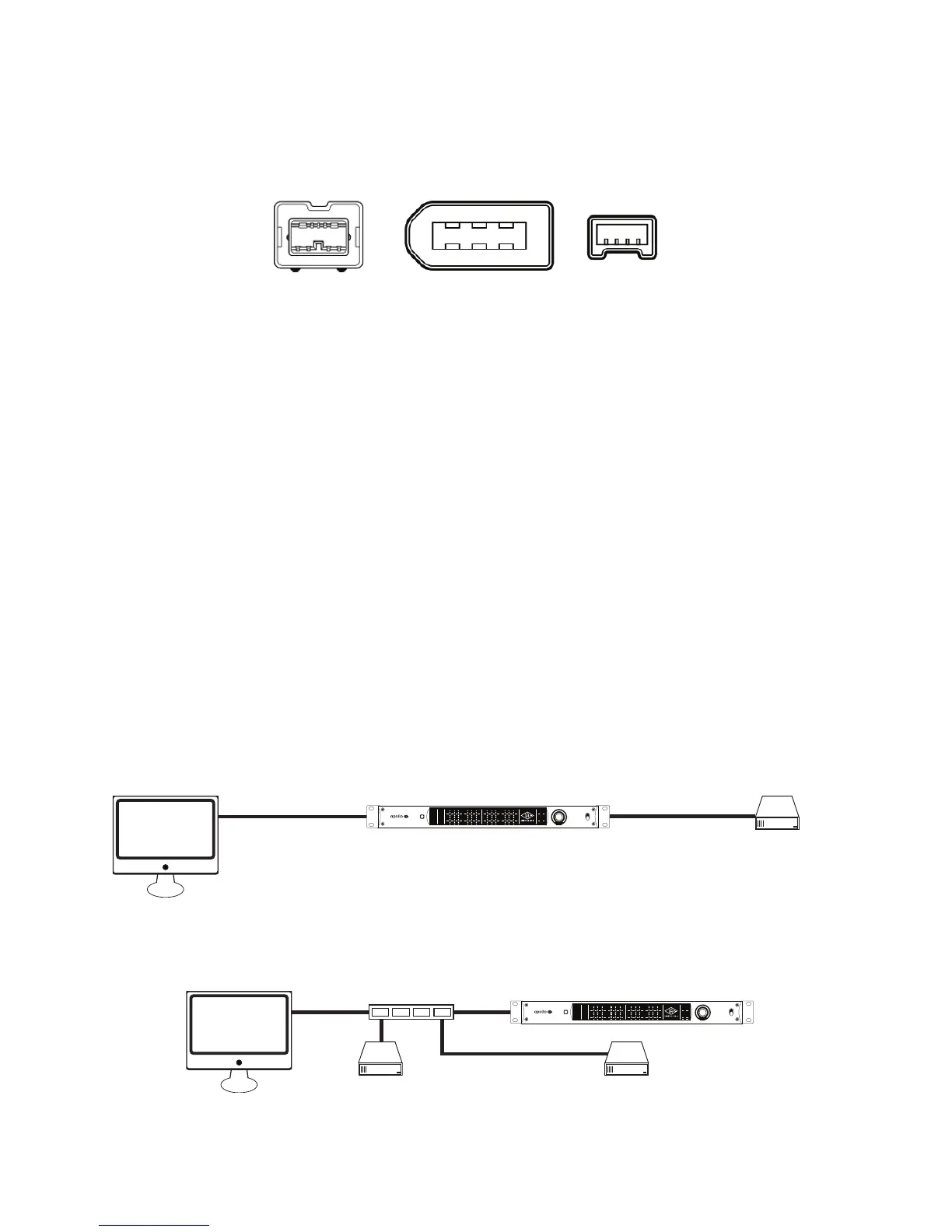
FireWire Connectors
FireWire 800 and FireWire 400 devices use different connectors, as illustrated below. This helps to differentiate
between the two device speeds (the connectors are not interchangeable).
FireWire 400 connectors
FireWire 400 devices typically have two types of connector: 4-pin and 6-pin. The small 4-pin FireWire 400
connector is common on digital camcorders and Windows notebook computers. The 6-pin connector is more
common with hard drives and audio devices.
FireWire 800 connector
FireWire 800 devices use a 9-pin connector. 9-pin to 6-pin FireWire adapter cables are available to connect
FireWire 800 devices to a FireWire 400 bus (with half the bandwidth).
Apollo 16 has two FireWire 800 ports to facilitate easy daisy chaining with other FireWire devices.
FireWire Repeaters and Chains
FireWire devices can be connected to each other serially in a “daisy chain,” connected to a central device such
as a computer with multiple FireWire ports or a peripheral FireWire repeater, or any combination of the two in a
“tree chain” topology.
Apollo 16 can function as a FireWire repeater, by using the unused port on the unit to connect other FireWire
devices. Note that Apollo 16 does not supply FireWire bus power to downstream devices.
The examples below show a few of the many interconnection possibilities using daisy chains and repeaters.
FW 800 (9-pin) FW 400 (6-pin) FW 400 (4-pin)
FireWire bus connections via repeater
Computer
Hard Drive
Hard Drive
Apollo 16
FW Repeater
METER I/O
POWER
OFF
METER
1 2 3 4 5 6 7 8
C
0
-6
-3
-9
-12
-15
-18
-21
-27
88.2
RATE
44.1
48
176.4
96
192
9 10 11 12 13 14 15 16
C
0
-6
-3
-9
-12
-15
-18
-21
-27
HOST
CLOCK
INT
EXT
METER
IN
OUT
MONITOR
1 2
C
0
-6
-3
-9
-12
-15
-18
-21
-27
FireWire bus connections via daisy chain
Hard Drive
Computer
Apollo 16
METER I/O
POWER
OFF
METER
1 2 3 4 5 6 7 8
C
0
-6
-3
-9
-12
-15
-18
-21
-27
88.2
RATE
44.1
48
176.4
96
192
9 10 11 12 13 14 15 16
C
0
-6
-3
-9
-12
-15
-18
-21
-27
HOST
CLOCK
INT
EXT
METER
IN
OUT
MONITOR
1 2
C
0
-6
-3
-9
-12
-15
-18
-21
-27
Computer
FireWire bus connections via repeater and daisy chain in a “tree chain”
Apollo 16
FW Repeater
Hard Drive
Hard Drive
METER I/O
POWER
OFF
METER
1 2 3 4 5 6 7 8
C
0
-6
-3
-9
-12
-15
-18
-21
-27
88.2
RATE
44.1
48
176.4
96
192
9 10 11 12 13 14 15 16
C
0
-6
-3
-9
-12
-15
-18
-21
-27
HOST
CLOCK
INT
EXT
METER
IN
OUT
MONITOR
1 2
C
0
-6
-3
-9
-12
-15
-18
-21
-27
This FireWire bus runs @ 400 MB because host computer is FW400
FW400
FW800 FW800
METER I/O
POWER
OFF
METER
1 2 3 4 5 6 7 8
C
0
-6
-3
-9
-12
-15
-18
-21
-27
88.2
RATE
44.1
48
176.4
96
192
9 10 11 12 13 14 15 16
C
0
-6
-3
-9
-12
-15
-18
-21
-27
HOST
CLOCK
INT
EXT
METER
IN
OUT
MONITOR
1 2
C
0
-6
-3
-9
-12
-15
-18
-21
-27
This FireWire bus runs @ 400 MB because 1st device in chain is FW400
FW800
FW800 FW800
FW400
FW bus @ 400 MB
METER I/O
POWER
OFF
METER
1 2 3 4 5 6 7 8
C
0
-6
-3
-9
-12
-15
-18
-21
-27
88.2
RATE
44.1
48
176.4
96
192
9 10 11 12 13 14 15 16
C
0
-6
-3
-9
-12
-15
-18
-21
-27
HOST
CLOCK
INT
EXT
METER
IN
OUT
MONITOR
1 2
C
0
-6
-3
-9
-12
-15
-18
-21
-27
This FireWire bus runs @ both 800 MB and 400 MB because the
FW400 device is located AFTER the FW800 devices in the chain
FW bus @ 800 MB FW bus @ 400 MB
FW800
FW800 FW800 FW400
METER I/O
POWER
OFF
METER
1 2 3 4 5 6 7 8
C
0
-6
-3
-9
-12
-15
-18
-21
-27
88.2
RATE
44.1
48
176.4
96
192
9 10 11 12 13 14 15 16
C
0
-6
-3
-9
-12
-15
-18
-21
-27
HOST
CLOCK
INT
EXT
METER
IN
OUT
MONITOR
1 2
C
0
-6
-3
-9
-12
-15
-18
-21
-27