Apollo 16 Hardware Manual FireWire Basics 25
Combining FireWire 400 and 800 devices on a FireWire 800 bus
It is possible to configure a FireWire bus to run at both FireWire 400 and FireWire 800 speeds simultaneously
if the host computer bus is FireWire 800, supporting maximum throughput with a combination of FireWire 400
and FireWire 800 devices. This is accomplished by putting any/all FireWire 400 devices AFTER any/all FireWire
800 devices in a daisy chain or tree chain. If (and only if) FireWire 400 devices are attached to a FireWire 800
bus after the end of all FireWire 800 devices in a daisy chain or tree chain, the FireWire 800 devices will operate
at 800 megabits while the FireWire 400 device operates at 400 megabits. The diagram below illustrates the
recommended configuration when Apollo 16 is sharing a FireWire 800 bus with FireWire 400 devices.
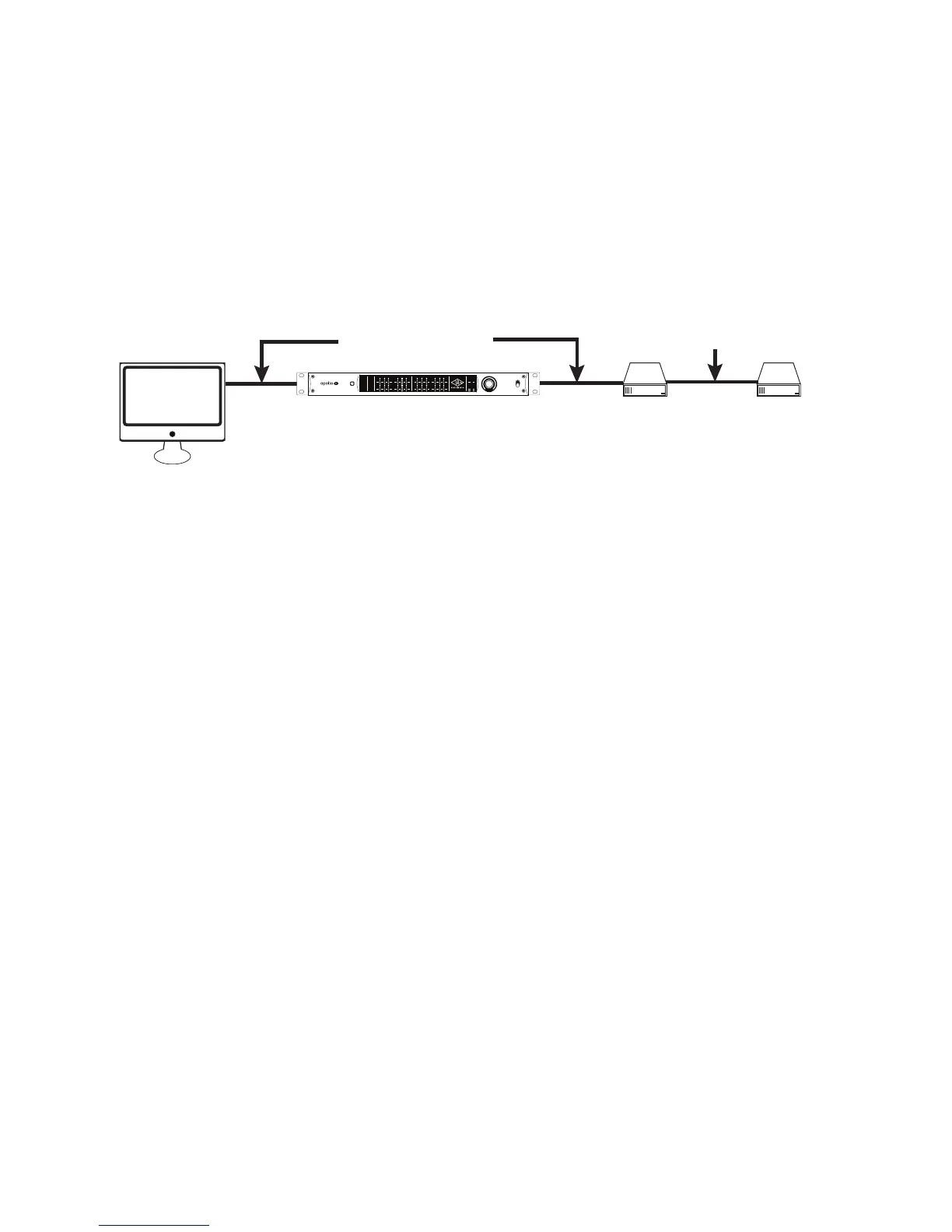
Recommended Mixed Speed Setup
The example above shows the correct method of interconnecting FireWire 800 and FireWire 400 devices to a
FireWire 800 computer bus. Any mixture of daisy chains, repeaters, and/or tree chains may be used, as long as
all the FireWire 400 devices are placed after all the FireWire 800 devices.
FireWire with Thunderbolt
When Apollo 16 is connected to the computer via the Thunderbolt Option Card, both of Apollo 16’s FireWire ports
remain active and they can be connected to FireWire peripheral devices such as hard drives. For an illustration
of this configuration, see “Thunderbolt Setup” on page 19.
FireWire bus connections via repeater
Computer
Hard Drive Hard Drive
Apollo 16
FW Repeater
METER I/O
POWER
OFF
METER
1 2 3 4 5 6 7 8
C
0
-6
-3
-9
-12
-15
-18
-21
-27
88.2
RATE
44.1
48
176.4
96
192
9 10 11 12 13 14 15 16
C
0
-6
-3
-9
-12
-15
-18
-21
-27
HOST
CLOCK
INT
EXT
METER
IN
OUT
MONITOR
1 2
C
0
-6
-3
-9
-12
-15
-18
-21
-27
FireWire bus connections via daisy chain
Hard DriveComputer
Apollo 16
METER I/O
POWER
OFF
METER
1 2 3 4 5 6 7 8
C
0
-6
-3
-9
-12
-15
-18
-21
-27
88.2
RATE
44.1
48
176.4
96
192
9 10 11 12 13 14 15 16
C
0
-6
-3
-9
-12
-15
-18
-21
-27
HOST
CLOCK
INT
EXT
METER
IN
OUT
MONITOR
1 2
C
0
-6
-3
-9
-12
-15
-18
-21
-27
Computer
FireWire bus connections via repeater and daisy chain in a “tree chain”
Apollo 16
FW Repeater
Hard Drive
Hard Drive
METER I/O
POWER
OFF
METER
1 2 3 4 5 6 7 8
C
0
-6
-3
-9
-12
-15
-18
-21
-27
88.2
RATE
44.1
48
176.4
96
192
9 10 11 12 13 14 15 16
C
0
-6
-3
-9
-12
-15
-18
-21
-27
HOST
CLOCK
INT
EXT
METER
IN
OUT
MONITOR
1 2
C
0
-6
-3
-9
-12
-15
-18
-21
-27
This FireWire bus runs @ 400 MB because host computer is FW400
FW400
FW800 FW800
METER I/O
POWER
OFF
METER
1 2 3 4 5 6 7 8
C
0
-6
-3
-9
-12
-15
-18
-21
-27
88.2
RATE
44.1
48
176.4
96
192
9 10 11 12 13 14 15 16
C
0
-6
-3
-9
-12
-15
-18
-21
-27
HOST
CLOCK
INT
EXT
METER
IN
OUT
MONITOR
1 2
C
0
-6
-3
-9
-12
-15
-18
-21
-27
This FireWire bus runs @ 400 MB because 1st device in chain is FW400
FW800
FW800 FW800
FW400
FW bus @ 400 MB
METER I/O
POWER
OFF
METER
1 2 3 4 5 6 7 8
C
0
-6
-3
-9
-12
-15
-18
-21
-27
88.2
RATE
44.1
48
176.4
96
192
9 10 11 12 13 14 15 16
C
0
-6
-3
-9
-12
-15
-18
-21
-27
HOST
CLOCK
INT
EXT
METER
IN
OUT
MONITOR
1 2
C
0
-6
-3
-9
-12
-15
-18
-21
-27
This FireWire bus runs @ both 800 MB and 400 MB because the
FW400 device is located AFTER the FW800 devices in the chain
FW bus @ 800 MB FW bus @ 400 MB
FW800
FW800 FW800 FW400
METER I/O
POWER
OFF
METER
1 2 3 4 5 6 7 8
C
0
-6
-3
-9
-12
-15
-18
-21
-27
88.2
RATE
44.1
48
176.4
96
192
9 10 11 12 13 14 15 16
C
0
-6
-3
-9
-12
-15
-18
-21
-27
HOST
CLOCK
INT
EXT
METER
IN
OUT
MONITOR
1 2
C
0
-6
-3
-9
-12
-15
-18
-21
-27