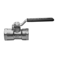
Apollo Full Port & Standard Port Three Piece Ball Valves
Installation, Operation, & Maintenance Guide
Complete the fastener torqueing sequence with one final check
going around the bolt pattern clockwise at the specified torque
level.
Complete the reassembly by installing the handle, lock plate and
stops, or the actuation components as applicable.
Reassembly for Valves with -EF Packing
*NOTE: For Chlorine, Oxygen and similar services, assemble
without lubricants.
Begin the reassembly process by cleaning each of the component
parts with a clean lint-free towel or cloth.
Place the stem bearing on the stem, and insert the stem into the
valve body stem bore. Place the flats on top of the stem
perpendicular to the centerline of the body.
*Lightly lubricate the stem with MorOil FLO 1150 or approved
equivalent unless valve service requires dry assembly. Packing
shall be pre-compressed two rings at a time. For packing sets that
have an odd number of packing rings, the final packing pre-
compression will be compressing a single ring.
Install two rings of the -EF option packing. Offset packing rings
such that each consecutive ring has 180° of separation between
the skive cuts in the packing rings. Use the appropriate
compression tool listed in Table 5 (except as noted), and the
valve’s packing retention system (gland, gland plate, and stem
packing adjustment fasteners) as the means for packing pre-
compression. Carefully insert the appropriate compression tool
into the stuffing box; avoid scratching the stuffing box or
compressing the packing by hand.
Lubricate the stem packing adjustment fasteners. Install the
packing gland, gland plate, and stem packing adjustment
fasteners in the order given. Ensure the gland and gland plate
remain parallel to the valve body and centered about the valve
stem. Torque the stem packing adjustment fasteners to the
applicable value specified in Table 1 or Table 2, as applicable.
Ensure that the gland plate does not make contact with the valve’s
mounting pad or anything that could prevent desired compression
of the stem packing. Remove the packing retention system and
compression tool. Repeat the packing installation and packing
pre-compression process as listed above until the entire packing
set has been pre-compressed. If the final pre-compression does
not require a compression tool, then the packing retention system
does not have to be removed after the final pre-compression has
been performed.
Place the internal grounding spring on the stem and carefully insert
the ball into the body. Using the stem, rotate the ball to the open
position. Verify the characterized profile will be facing the upstream
end cap by nothing the flow direction arrow etched on the body.
Refer to Figure 2.
*Apply a small amount of service compatible lubricant to the new
seats and install them in the valve body. Seats may be installed dry
however some assembly lubricant is desirable and acts to hold the
seats in place during the assembly process.
*Apply a small amount of compatible grease to the body side of the
gasket. This acts to hold the gasket in place for the assembly
process, but is not required.
Lubricate and install the body bolts finger tight at this time.
Cycle the valve open and closed several times to ensure all
components are properly aligned.
Using a criss-cross pattern, in three approximately equal steps,
torque the body bolts to the value given in Table 3 or Table 4, as
applicable. Cycle the valve open and closed between each step to
ensure continued smooth operation.
Complete the fastener torqueing sequence with one final check
going around the bolt pattern clockwise at the specified torque
level.
Complete the reassembly by installing the handle, lock plate and
stops, or the actuation components as applicable.
 Loading...