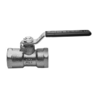
Apollo Full Port & Standard Port Three Piece Ball Valves
Installation, Operation, & Maintenance Guide
The ball can now be removed from the body cavity. Maintain
internal grounding spring for reassembly.
To remove stem packing:
Remove components as described in above section.
Remove the following applicable parts based on valve options
purchased: handle and associated hardware, stem packing
adjustment nuts or screws, Belleville washers, gland plate and
packing gland.
Press stem with stem bearing down into body and remove.
Remove the stem packing using care not to scratch or scar the
stem packing box.
Inspection
Thoroughly clean all components in preparation for inspection.
Inspect the sealing face of end caps for scratches and pits. If either
of these is apparent and can be removed with #120 or finer grit
emery cloth, replacement will not be necessary. If replacement of
the endcaps becomes necessary, then replacement of the entire
valve is recommended.
Inspect stem packing contact surfaces for scratches and pits. If
either of these is apparent and can be removed with #120 or finer
grit emery cloth, body replacement will not be necessary. Deep
scratches running down the side of the stuffing box or excessive
pitting will necessitate the replacement of the valve body.
Inspect the ball in the same manner. Replace the ball if necessary.
Inspect remainder of body interior for pitting or corrosion and
replace either if excessive.
Inspect all parts for wear due to erosion or abrasion and replace if
excessive.
NOTE: Carbon steel component parts are zinc phosphate treated
and oil dipped to improve fatigue properties and increase wear
and corrosion resistance.
Reassembly for Valves with Graphite Packing
*NOTE: For Chlorine, Oxygen and similar services, assemble
without lubricants.
Begin the reassembly process by cleaning each of the component
parts with a clean lint-free towel or cloth.
Place the stem bearing on the stem, and insert the stem into the
valve body stem bore. Place the flats on top of the stem
perpendicular to the centerline of the body.
Lubricate the stem packing adjustment studs or screws.
Install the stem packing, packing gland, gland plate, Belleville
spring washers (refer to Figure 1 for arrangement), and stem
packing adjustment nuts or screws in the order given.
Tighten the fasteners evenly to the torque in Table 1 or Table 2, as
applicable, ensuring the gland plate remains parallel to the valve
body. Do not overtighten, as this will result in excessive operating
torque and shortened packing life.
Place the internal grounding spring on the stem and carefully insert
the ball into the body. Using the stem, rotate the ball to the open
position. Verify the characterized profile will be facing the upstream
end cap by noting the flow direction arrow etched on the body.
Refer to Figure 2.
*Apply a small amount of service compatible lubricant to the new
seats and install them in the valve body. Seats may be installed dry
however some assembly lubricant is desirable and acts to hold the
seats in place during the assembly process.
*Apply a small amount of compatible grease to the body side of the
gasket. This acts to hold the gasket in place for the assembly
process, but is not required.
Lubricate and install the body bolts finger tight at this time.
Cycle the valve open and closed several times to ensure all
components are properly aligned.
Using a criss-cross pattern, in three approximately equal steps,
torque the body bolts to the value given in Table 3 or Table 4, as
applicable. Cycle the valve open and closed between each step to
ensure continued smooth operation.
 Loading...