17 AIM-1SL & AIM-2SL Hardware Manual
© 2011 Apollo Security Inc.
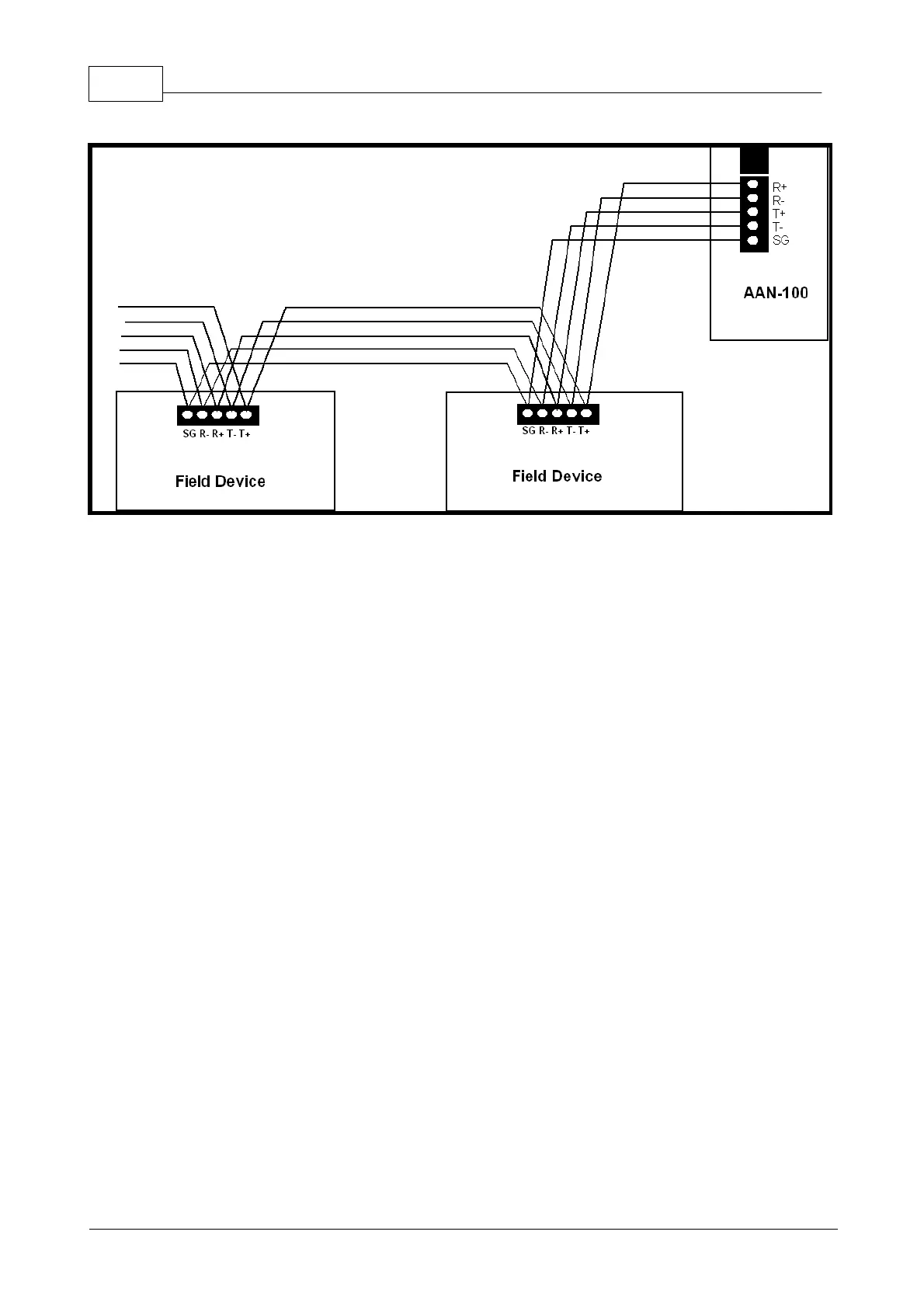
Figure 3.4.1.2 RS-485 Device Connections.
The AAN-100 serves as the master on the line and the
field devices are slaves. The receive lines of the master are wired to the transmit lines of the slaves, and the
receive lines of the slaves are wired to the transmit of the master.
3.5 Card Reader Wiring
Up to two card readers can be connected to the AIM-1/2SL. Card readers with standard Wiegand output are
supported, including magnetic stripe, proximity, bar code, smart card, biometric, keypad, etc. It is not
necessary for the readers to be identical on each connection port, i.e. two different reader types can be used
simultaneously.
Each reader connection consists of connection terminals for VDC Output and Ground, Data 1 Signal, Data 0
Signal, Beeper control, and multiple LED control (red, green, and yellow). The wiring to the reader should be
made using 24 AWG shielded cable with 4 twisted pairs (Belden 9504 or equivalent). Do not exceed 500 feet
(152 m) between the AIM-1/2SL and reader. Connect the shield drain wire of the cable at the GND terminal
of the appropriate reader connector on the AIM-1/2SL. Carefully insulate the drain wire with sleeving for a
reliable installation.
Power for the reader connection (VDC) is derived from the power input (VIN) for the AIM-1/2SL and is
distributed between the reader connections. Thus, voltage to the reader power connection will roughly equal
the voltage supplied to the AIM-1/2SL power input. There must be sufficient power to supply the load of all
readers as well as for the AIM-1/2SL itself (+12 to +24VDC @ 250 mA). If the readers have a greater total
power requirement, or if there are other wiring concerns, external power supplies should be used to power
the readers. In this case, only connect the reader power lines to the external power supply; do not connect
the reader to two power supplies.
For basic operation of the reader, at a minimum the Data 0 and Data 1 wires must be connected from the
reader to the AIM-1/2SL and power supplied to the reader. LED and beeper control lines do not have to be
connected, but in this case, the LEDs and beeper may not function on the reader.