30System Wiring
© 2011 Apollo Security Inc.
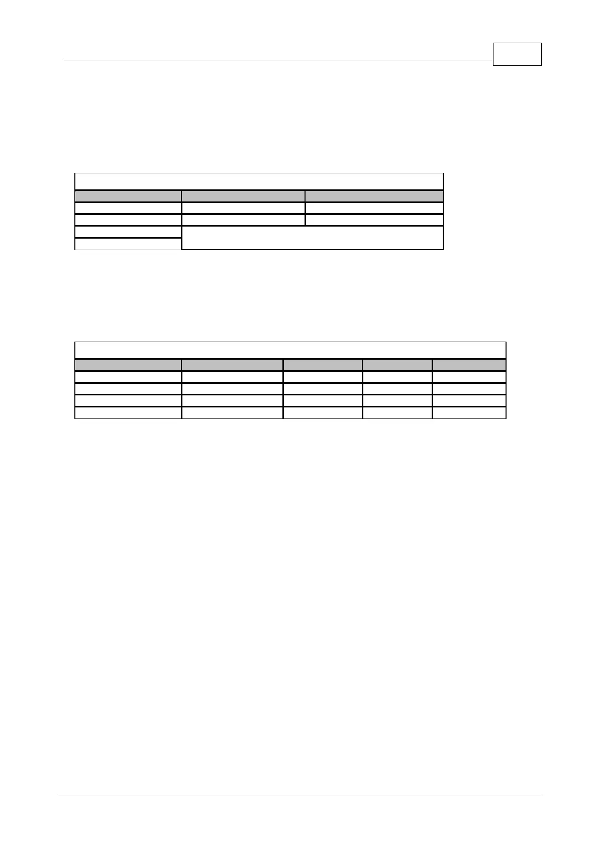
Figure 3.7.4:
ADA-10 Hardware Layout
On the ADA-10, the jumpers must be cut using wire cutters to assign the group/function. DO NOT CUT THE
JUMPERS FLUSH WITH THE SURFACE OF THE ADA-10 AS IT MAY BE NECESSARY RECONNECT
THEM LATER IF THE WRONG JUMPERS HAVE BEEN CUT
*This group does not function in Paired Mode!
Table 3.7.3:
ADA-10 Reader Setting
Next, the function of the ADA-10 must be defined. This is done by cutting THREE of the four jumpers for
Output Select on the ADA-10. For each group, there are four possible settings:
Table 3.7.4:
ADA-10 Function Setting
The above functions will work the same for each reader. Thus, if reader 2 is selected (G1=CUT G2=NOT
CUT), and the function Strike Relay is selected (1=NOT CUT 2=CUT 3=CUT 4=CUT), the ADA will function
as the strike relay for Reader 2. In Paired Reader Mode, any relays set for reader 2 will be non-functional!
Reader 3 and 4 never have a function with the AIM-1/2SL!
3.8 General Alarm Inputs
The AIM-1/2SL provides one general alarm input. The wiring to the input should be made with twisted pair
24 AWG wire. If this input is not used, it should be ‘jumpered’ using a 1” (25 mm) long piece of wire
connecting the two terminals to form a closed circuit. This will prevent an alarm condition being reported to
the host.