Specifications
Apollo SL30 Installation Manual
SERIAL INTERFACE
RS-232...................................................... Defined in Appendix E - Serial Interface
Specifications
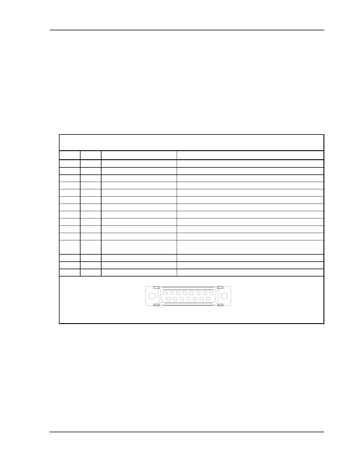
REAR CONNECTOR PINOUT
The SL30 includes two rear panel connectors, a 15-pin for the Comm interface connections
and a 37-pin for the rear panel connections. The pinout for the connectors is listed in the
following tables.
Table 2 - Comm Interface Connector Pinout
Pin # I/O Connection Function
1 I Power + Main DC power input
2 I Reserved Do not connect
3 O Reserved Do not connect
4 I TxKey Transmit enable key, pulled low to transmit
5 -- NC Do not connect
6 O Speaker Speaker terminal output
7 I Mic ground Microphone input ground connection
8 I Mic 1 Microphone input #1
9 I Power ground Main power ground input
10 I Reserved Do not connect
11 O Reserved Do not connect
12 I Intercom select Intercom function select, pulled low to turn on the intercom
function
13 O Audio ground Speaker and headphone ground connection
14 O Headphone Headphone terminal output
15 I Mic 2 Microphone input #2
1 8
9 15
Viewed from rear of unit