Do you have a question about the Apollo SL40 and is the answer not in the manual?
This manual provides performance checkout, troubleshooting, disassembly, and test procedures for the SL40 unit.
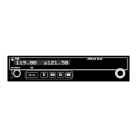
Details the Apollo SL40 as a 760 channel VHF Comm transceiver and part of the Apollo slimline series.
Lists the key capabilities of the SL40 Comm, including channels, display, intercom, and audio amplifier.
Outlines the TSOs and FCC requirements the Apollo SL40 is designed and tested to meet.
Provides essential guidelines for safely handling the SL40, focusing on electrostatic discharge (ESD) protection.
Details measures to protect SL40 components from mechanical and electrostatic discharge damage.
Emphasizes care when handling ESDS components and grounding procedures.
Provides instructions for returning SL40 components, stressing the use of anti-static packaging.
Lists required tools, like hex and Phillips screwdrivers, and essential test equipment for SL40 maintenance.
Briefly describes the scope of field maintenance for the SL40, limited to board replacement.
Details essential precautions for handling SL40 circuit boards in an ESD safe environment.
Outlines initial tests to perform before removing the SL40 from the aircraft to isolate problems.
Explains how to access and use built-in system functions for isolating Comm problems, including displays and adjustments.
Displays the COM software version.
Displays the signal strength of received signals using an 8-bit value.
Displays the noise level of the received audio using an 8-bit value.
Allows display and adjustment of the headphone audio level.
Allows display and adjustment of the intercom squelch threshold level.
Allows display and adjustment of the intercom audio level.
Allows display and adjustment of the sidetone audio level.
Allows display and adjustment of the lockout mode, which affects Comm functions.
Explains how to use test mode for display and control testing, and accessing calibration functions.
Details the procedure to enable the built-in test mode by pressing specific buttons while switching on the unit.
Describes knob usage for selecting test functions and pages in test mode.
Identifies the first page displayed when entering test mode.
Tests the display and LED indicators by sequencing through character segments.
Tests front panel control inputs, indicating button presses and squelch knob status.
References figures showing the schematic and graphic presentation of the SL40 transceiver test setup.
Details procedures to isolate SL40 problems to the Com Main board level and lists operating specifications for tests.
Defines expected transmitter performance specifications including output power, frequency range, tolerance, and modulation.
Details the procedure for measuring transmitter frequency error using the HP 8920.
Explains how to measure transmitter power output using the HP8920 without MIC audio input.
Describes measuring transmitter modulation percentage using the HP8920 with a 1000 Hz tone input.
Details measuring SNR by modulating the transmitter with a 1000 Hz tone and using the HP8920 SNR function.
Explains how to measure transmitter audio distortion using the HP8920 with a 1000 Hz tone at 85% modulation.
Defines expected receiver performance specifications, including class, frequency range, sensitivity, and selectivity.
Details testing speaker audio output level and distortion using the HP8920.
Explains how to measure receiver sensitivity by reducing signal generator amplitude until a 6 dB SINAD value is displayed.
Details procedures for disassembling and reassembling the SL40 unit, focusing on component removal and replacement.
Provides step-by-step instructions for removing the Com Main board from the SL40 unit.
Lists field replaceable components for the SL40 with their part numbers and quantities.
Lists field replaceable components for the SL40 with their part numbers and quantities.
Instructs users to contact the II Morrow Service Department for RMA and shipping instructions.
Provides guidelines for packaging SL40 components for shipment to prevent damage.
Provides contact information for II Morrow Inc. for technical assistance with the Apollo SL40.
Provides procedures for final verification and checkout of the SL40 before returning it to service.
Verifies proper repair, component installation, and function settings, documenting details on the Test Data Sheet.
Retests the SL40 after component replacement to ensure all functions are operating properly before aircraft reinstallation.
Instructs to perform the display test and record results on the Test Data Log sheet.
Instructs to perform the controls test and record results on the Test Data Log sheet.
Instructs to perform transmitter tests and record results on the Test Data Log sheet.
Instructs to perform receiver tests and record results on the Test Data Log sheet.
Verifies proper cable security, shield connection, and aircraft control interference.
Completes post installation checkout procedures after unit reinstallation in the aircraft.
Explains how to adjust the sidetone volume using the built-in test mode.
Recommends a flight test for final installation verification, checking performance at range.
| Channel Spacing | 25 kHz |
|---|---|
| Channels | 760 |
| Voltage | 13.75 V DC |
| Current Consumption (receive) | 0.5 A |
| Type | VHF Transceiver |
| Frequency Range | 118.00 MHz to 136.975 MHz |
| Modulation | AM |