Troubleshooting
22 Apollo SL40 Field Maintenance Manual
3. Tilt the SL40 cover so the front edge slides under the tab on the display bezel, and
position the cover so the screw holes are aligned with the PEM nuts. Secure the cover
with nine 4-40x3/16” flat head screws.
REPLACEABLE COMPONENTS
The SL40 field replaceable components are listed by II Morrow part number in Table 1.
Replacement policy and information on proper packaging of the SL40 components for
shipment is given in subsequent paragraphs.
COMPONENT LISTING
The components of the SL40 that are considered to be field replaceable and for which test
and replacement procedures are provided are listed in Table 1.
Table 1 Replaceable Components
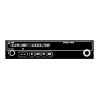
430-6040-2xx Apollo SL40 Comm Transceiver
Part # Description Qty
*415-7000-10 SP96 Com Display Board 6010 1
415-7002-00 VHF Com Main Board 6011 1
*Although the Com Display board is the actual replaceable component, assembly
considerations dictate that the complete Display assembly be returned for replacement.
REPLACEMENT POLICY
When troubleshooting procedures identify a failed component in the SL40, contact the
II Morrow Service Department for a Return Material Authorization (RMA) number and
shipping instructions. Do not return the component without an RMA. Instructions for
contacting the factory are given on page 22
PACKAGING FOR SHIPMENT
The SL40 circuit boards are subject to both mechanical and electrical damage when
improperly handled. These components must be packaged for shipment in anti-static
bags, to protect against electrostatic damage, and a sturdy protective box, to prevent
mechanical damage during shipment. Ideally, the component to be returned should be
packaged in the same shipping material that the replacement component is shipped in.
CONTACTING THE FACTORY FOR ASSISTANCE
If the Apollo SL40 unit fails to operate despite troubleshooting efforts, contact the II Morrow
factory for assistance.
II Morrow Inc.
2345 Turner Rd. SE
Salem, Oregon 97302
USA

 Loading...