6 3
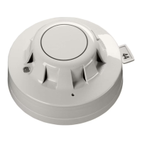
Fig 4 Flame detector wiring connections
Quantities Required and Positioning of Detectors
The number of detectors required and their positioning depends on:
• the anticipated size of the fl ame
• the distance of the fl ame from the detector
• the angle of view of the fl ame detector
The XP95 fl ame detector is designed to operate to Class 1 performance as defi ned in EN54:
Part 10. The detector will, therefore, detect a yellow fl ickering fl ame of approximately 0.1m²
or a clear fl ame of 0.25m² at 25m.
In fact, the fl ame detector will detect fi res at distances of up to 40 metres, but the fl ame size
at such distances needs to be proportionally greater in order to be sure of reliable detec-
tion. Thus the yellow fl ickering fl ame that can be detected at 25m, provided that its size is
not less than 0.1m², will have to be 0.4m² in order to be detected at 40 metres. In a rectan-
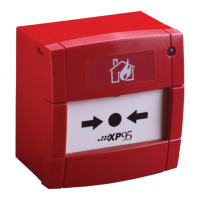
gular room the distance from the fl ame detector to the fi re is calculated by the formula:
L² + W² + H²
In the example shown in Fig 1 the room in which the fl ame detector is to be installed meas-
ures 20m x 10m x 5m; the distance from the detector to the fl ame will therefore be:
20² + 10² + 5²
= 22.9m
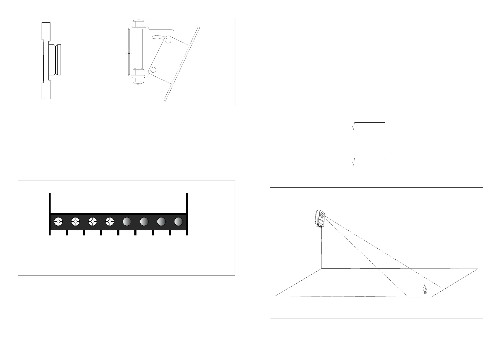
Fig 3 Mounting plate, supplied with detector, and optional bracket, part no 29600-203
The adjustable mounting bracket is used wherever it is necessary to adjust the viewing
angle up or down or left to right. It has two fi xing holes of 6.35mm diameter at 58mm
centres.
Flame detectors should be fi tted to solid walls or to rigid constructions that do not move
and are not subject to vibration.
Wiring
The fl ame detector has fi ve connections: Line 1, Line 2, +Remote, –Remote and functional
earth/screen. The connections are accessed by removing the front plate of the fl ame
detector. The cable is passed through the gland at the base of the detector. See Fig 4 for
connection diagram.
L2+ L1- R+ R-
Fig 1 Calculation of distance from detector to fl ame
Height
Width
Length
Terminal Descriptions
1 +L2 +Line IN and OUT Terminals 6 to 8 are not used
2 –L1 –Line IN and OUT
3 +R +Remote LED
4 –R –Remote LED
5 SCREEN Functional Earth/Screen (Isolated)