iMac (21.5-inch, Late 2009) — General Troubleshooting 26
2010-11-18
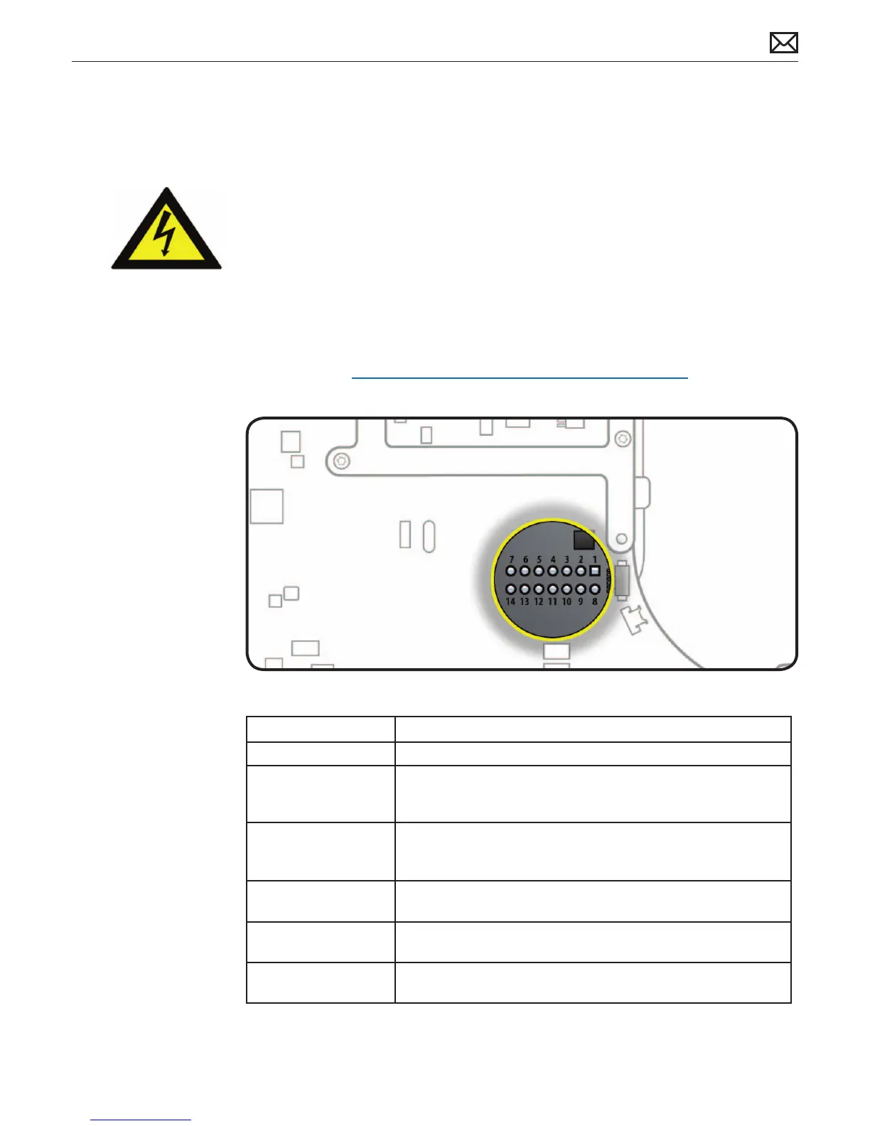
Logic Board Test Points
Test points, which can be used to verify proper power ow, are accessible on logic board when
LCD panel is removed. All voltages given in Troubleshooting Symptom Charts assume that
computer is plugged into a known-good power outlet with a known-good AC cable. Some
guidelines for using test points:
• Warning: HIGH VOLTAGE: Use extreme caution when live testing!
• Do NOT lean over or touch the power supply area during live testing.
• Keep your ngers behind nger guards on test probes when measuring.
• Turn dial of voltmeter/multimeter to measure DC (direct current, usually indicated by a solid
horizontal line over dashes). If your voltmeter requires a set voltage range, choose a DC
range that includes the voltage you are measuring.
• Connect black probe to ground. Connect red probe to test point and verify voltage.
For more info, see kBase #HT3250: Diagnostics: Using a digital multimeter
Logic Board Test Point Function
Pin 1 Ground
Pin 4 Standby 12V power (permanent power coming from power supply
and present as long as AC cable is connected, even if computer is
o); corresponds to LED #1
Pin 6 Backlight Control pulse width modulated signal (from logic board
to LED backlight board, to adjust the backlight level setting
according to user setup)
Pin 11 12V Run-Mode power to logic board (coming from power supply,
present as long as system is on or asleep); corresponds to LED #2
Pin 12 Power On Request signal (from logic board to power supply when
power button is pressed)
Pin 13 Backlight Enable (signal from logic board to Backlight Controller
board, to enable backlight
 Loading...