CSPP Capacitor Charging Unit Operation Manual
_________________________________________________________________________________________________________
__________________________________________________________________________________________________________
Page 13 of 59
If the unit has recently been moved from a cold environment to a warm one, condensation may
have developed, which may cause arcing in high voltage equipment. The operator is advised to
switch the unit on and run the fans for 10-15 minutes before allowing the high voltage to be
switched on. This will allow the unit to warm up to the room temperature, and any condensation
will disperse.
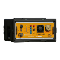
Power Up
When suitably connected to ground, the transducer and AC mains, and the transducer is in the
water, the power can be applied using the ON / OFF switch and circuit breaker. The fans will run,
and the HV OFF / RESET button will illuminate. Select the appropriate power output required and
press the RESET button to reset the internal circuitry. Press the HV ON button: there will be a
small delay before the HV relays engage, and then the high voltage will come on as indicated by
the illuminated HV ON switch. Any changes in system parameters (such as power change) will
cause the HV to switch OFF, and the unit will need to be RESET before the HV can be switched on
again. If the INTERLOCK indicator illuminates, check the HV plug / HV junction box.
Trigger Input
Trigger input is by BNC connector. The unit accepts +ve trigger (triggers on rising edge) 5 - 20
volts. Opto-isolated, or by contact closure, as controlled by the KEY switch. (OUT for +ve key, IN
for contact closure.) The manual key button can be used too and this also shows, by illumination,
when a key pulse has been accepted. (A lockout circuit limits the unit to around 6PPS maximum.)
Local / Remote
The LOCAL / REMOTE switch allows connection of remote box for operation from the laboratory or
instrument room. Using the remote box is achieved by turning the LOCAL / REMOTE switch to
remote. The high voltage can only be turned on from the instrument room and not from the CSP-D
Unit. The high voltage OFF button is operational from the CSP-D Unit and remote box. The CSP
Unit can also be keyed from the remote box via a BNC socket. The remote also monitors the
status of the key detect circuitry, and the key
LED will only illuminate on reception of a valid key pulse within the CSP-D itself, thus the
operator can also see if the interconnection cable is OK. The remote also has a FAULT LED, as
well as high voltage ON and high voltage OFF indicators.
LOCAL Operation indicated by LED on – Switch OUT.
REMOTE Operation indicated by LED out – switch IN