EasyManua.ls Logo

Aprilaire 6000 Series - User Manual

Aprilaire 6000 Series
28 pages
Print Icon
To Next Page IconTo Next Page
Loading...
SAFETY INSTRUCTIONS
Read this entire installation manual before beginning installation of the Aprilaire 6000 Series Zone Control System. For questions call Aprilaire
customer support at (800) 334-6011 or visit AprilairePartners.com.
WARNING
1. 120 volts may cause serious injury from electrical shock. Leave power disconnected until installation is complete.
2. The system is designed for indoor use only. Do not expose any of the components to moisture.
WARNING
1. Turn o the system power before removing or installing any wires into the terminals of any component of the system. Wiring with a live
circuit can lead to electrical shorts that can damage components.
2. Installation must be done in accordance with all applicable codes.
3. Installer should touch a grounded metal object before handling the components of the system. This will prevent any static discharge that
may cause damage.
4. A 6000 Series Zone Control System may not control temperature properly unless the heating and cooling system is properly sized and
balanced.
5. Insucient air flow or excessive temperatures through the heating and cooling system could result in equipment damage. Refer to the
manufacturer’s recommendations for minimum safe airflow and temperature requirements.
6. Do not mount the 6000 Series Control or Sensors on any exterior wall or equipment supply ductwork.
7. Do not install the system components where temperatures exceed 158°F (70°C) or are below 32°F (0°C), non-condensing.
8. Improper system installation could cause water damage from frozen pipes. Check system operation after installation.
READ AND SAVE THESE INSTRUCTIONS
6000 Series Zone Control System
For models 6010, 6015, 6020, 6025, 6030, 6035,
6040, 6045, 6045M
Safety & Installation Instructions
1
Question and Answer IconNeed help?

Do you have a question about the Aprilaire 6000 Series and is the answer not in the manual?

Summary

SAFETY INSTRUCTIONS

Electrical Shock and General Safety

Crucial safety warnings regarding electrical hazards, moisture, and environmental conditions for installation.

SPECIFICATIONS

Technical Specifications and Dimensions

Details input ratings, maximum current, operating environment, and physical dimensions of the system components.

APPLICATIONS AND FEATURES

System Configurations and Capabilities

Lists available model configurations and highlights key system features like remote access and IAQ control.

LAYOUT AND TERMINALS

6000 Series Hub Components and Connections

Details the physical layout of the 6000 Series Hub, including terminal connections, LEDs, and buttons.

USER INTERFACES

6000 Series Control Home Screen

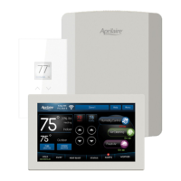
Explains the main screen layout and functions of the 6000 Series Control, showing temperature, humidity, and status.

6000 Series Sensor Interface

Describes the interface of the 6000 Series Sensor, displaying room temperature and temperature settings.

6000 SERIES HUB INSTALLATION

Location and Mounting Guidelines

Provides instructions on where to mount the 6000 Series Hub and how to attach it securely.

6000 SERIES HUB WIRING

Transformer Connections and Sizing

Details the power transformer requirements and wiring for the 6000 Series Hub, including damper calculations.

DAMPER WIRING

Damper Wiring Configurations

Explains how to wire different types of dampers (normally open/closed, power open/close) to the 6000 Series Hub.

SENSOR INSTALLATION AND WIRING

Outdoor and Discharge Air Temperature Sensors

Instructions for wiring and mounting the included outdoor and discharge air temperature sensors.

Optional Return Air Temperature Sensor

Guidelines for installing and wiring the optional return air temperature sensor.

HVAC EQUIPMENT WIRING DIAGRAMS

Furnace, Heat Pump, and Boiler Diagrams

Illustrates various wiring configurations for connecting the zone control system to different HVAC equipment types.

INDOOR AIR QUALITY WIRING DIAGRAMS

Humidifier, Dehumidifier, and Damper Wiring

Shows wiring diagrams for connecting IAQ devices like humidifiers, dehumidifiers, and dampers.

CONTROL AND SENSOR INSTALLATION

Mounting Location and Plate Installation

Details recommended locations and steps for mounting the 6000 Series Control and its sensors.

CONTROL AND SENSOR WIRING

Connecting Control to Hub

Step-by-step instructions for wiring the 6000 Series Control to the 6000 Series Hub.

Connecting Sensor to Hub

Step-by-step instructions for wiring the 6000 Series Sensor to the 6000 Series Hub.

INSTALLER SETUP AND CONFIGURATION

Installer Setup Menu and Navigation

Guides the installer through the initial setup menu, including accessing settings and using USB drives.

Installer Tools and Test Options

Explains the functions available in the Installer Tools menu, such as importing/exporting settings and performing tests.

General System Settings

Details general system settings like temperature scale and contractor information input.

THERMOSTAT SYSTEM SETTINGS

Equipment, Control, and Fan Settings

Configuration options for HVAC equipment type, control setup, and fan operation during heating.

Schedule, Recovery, and Display Options

Settings related to programmable schedules, progressive recovery, and display options for buttons.

THERMOSTAT SYSTEM SETTINGS CONTINUED

Sensor Offsets, Timing, and Staging

Adjustments for sensor offsets, minimum equipment run times, and compressor protection.

Differential and Service Reminders

Settings for stage differentials and HVAC service reminder recurrence.

ZONE SYSTEM SETTINGS

Zone Number, Staging, and Weighting

Configuration for the number of zones, staging logic, and zone precedence weighting.

DAT Sensor Limits and Downstaging

Settings for Discharge Air Temperature sensor limits and downstaging behavior.

HUMIDIFIER SYSTEM SETTINGS

Humidifier Installation and Mode Control

Settings for humidifier installation type, operating mode, and allowed operation.

Humidifier Reminders and Deadband

Configuration for humidifier reminders, change water panel messages, and humidity deadband.

IAQ SYSTEM SETTINGS

Dehumidifier Configuration and Limits

Settings for dehumidifier installation, cooling disable, overcooling limit, and reminders.

Air Cleaner Installation and Reminders

Settings for air cleaner installation and air filter change reminders.

FRESH AIR SYSTEM SETTINGS

Ventilation Setup and Calculations

Parameters for fresh air ventilation, including ASHRAE calculations and CFM settings.

Ventilation Temperature and RH Limits

Defines temperature and humidity limits for enabling or disabling fresh air ventilation.

WI-FI SETUP AND CONNECTIVITY

Connecting to a Wi-Fi Network via Control

Steps to connect the 6000 Series Control to a Wi-Fi network directly through its interface.

Connecting via Browser or App

Instructions for connecting the system using a web browser or the Aprilaire mobile application.

SENSOR AND TEST PROCEDURES

6000 Series Sensor Zone Selection

Process for selecting the zone number for the 6000 Series Sensor upon initial setup.

Installer Checkout Testing

Procedures for performing installer checkout tests using either the 6000 Series Control or Hub.

INSTALLER SETTINGS TABLES

Heat;Cool Equipment Installer Settings

Detailed installer settings for heat/cool HVAC equipment outputs and IAQ devices.

Heat Pump Installer Settings

Specific installer settings for heat pump HVAC equipment outputs and IAQ devices.

SEQUENCE OF OPERATION

Heat;Cool Changeover and DAT Limits

Explains the system's behavior during heat/cool changeover and the function of DAT sensor limits.

Emergency Heat, Fan, Heating, and Cooling

Describes operation modes including Emergency Heat, fan control, heating, and cooling sequences.

EQUIPMENT STAGING AND DUAL FUEL

Multistage Equipment Staging Logic

Details how the system stages multi-stage HVAC equipment based on zone calls or number of zones.

Dual Fuel Operation Control

Explains how outdoor temperature affects heat pump and auxiliary heat usage in dual fuel systems.

TROUBLESHOOTING GUIDE

Display and System Response Issues

Solutions for a blank display, unresponsive heating, or cooling systems.

Fan Operation and Wiring Checks

Troubleshooting steps for fan not turning on and general wiring checks.

LIMITED WARRANTY AND REGISTRATION

Warranty Terms and Exclusions

Outlines the warranty period, obligations, exclusions, and void conditions for the zone control system.

Warranty Registration Process

Instructions on how to register the Aprilaire product to activate warranty coverage.

Overview

The Aprilaire 6000 Series Zone Control System is a comprehensive solution for managing indoor climate and air quality across multiple zones. It is designed for models 6010, 6015, 6020, 6025, 6030, 6035, 6040, 6045, and 6045M.

Function Description

The system provides precise temperature control, indoor air quality management, and zone-specific climate adjustments. It integrates heating, cooling, humidification, dehumidification, air cleaning, and ventilation functionalities. The system prioritizes heating calls and manages opposing heating/cooling calls with a 20-minute changeover time limit. It also incorporates discharge air temperature (DAT) sensor limits to prevent equipment damage from overheating or freezing. Emergency Heat mode is available for heat pump systems, locking out the heat pump and utilizing auxiliary heat. Fan operation can be initiated by any zone, closing dampers for non-calling zones.

Important Technical Specifications

Input Ratings (6000 Series Hub):

  • Voltage: 18-30VAC 50/60 Hz

Maximum Current:

  • Damper output per zone (fused): 18VA at 158°F, 30VA at 90°F. Use 18 or 20 AWG solid (non-stranded) wire.

Environment:

  • 6000 Series Hub Temperature (operating): 32°F - 158°F
  • 6000 Series Control and Sensors (operating): 32°F – 120°F
  • Temperature (shipping): -30°F – 150°F
  • Humidity: 5% - 90%, non-condensing

Dimensions (in inches/mm):

  • 6000 Series Hub: 11.19 (284) H x 8.63 (219) W x 1.86 (47) D
  • 6000 Series Control: 4.38 (111) H x 7.11 (181) W x 1.06 (27) D
  • 6000 Series Sensor: 4.99 (127) H x 3.07 (78) W x 0.82 (21) D

Wiring Specifications:

  • 18-24 gauge thermostat wire for control and sensor connections.
  • Maximum distance for ODT and DAT sensors from the Hub is 300 feet.
  • Maximum distance for RAT sensor from the Hub is 300 feet.

Transformer Sizing:

  • Normally Open/Power Close Dampers (2-Wire): (Number of dampers that could be energized at one time x 10VA) + 10VA for 6000 Series System.
  • Power Open/Power Close Dampers (3-Wire): (Total number of dampers x 2.5VA) + 10VA for 6000 Series System.

Usage Features

Remote Access:

  • Downloadable app for iOS App Store and Google Play Store.

Climate Control:

  • Temperature Control: 7-day programmability, easy override of program schedules, progressive recovery, compressor protection.
  • Heat Blast®: Raises room temperature 3°F to 5°F with one touch.
  • One Touch Away: Sets thermostat to a predefined setpoint.
  • Staging: Configurable based on zone or number of zones calling, allowing for efficient multi-stage HVAC equipment operation.
  • Dual Fuel Operation: Utilizes outdoor temperature sensor for efficient heat pump and auxiliary heat management based on HIGH and LOW BALANCE POINT settings.

Indoor Air Quality (IAQ) Control:

  • Humidification: Automatic or manual control, with options for operation with or without the HVAC fan.
  • Dehumidification: With or without fan force, and an overcooling limit.
  • Event-Based™ Air Cleaning: Programmable air cleaning cycles.
  • Ventilation: With temperature and humidity limits, ASHRAE or timed setup.

Display and Interface:

  • Large touch screen with adjustable backlight.
  • Displays room temperature, room humidity, temperature setting, and outdoor temperature.
  • Wi-Fi indicator (strobes in setup mode).
  • Current date and time (automatically updated if connected to internet).

System Configuration:

  • Installer Setup Menu: Accessible upon first power-up or after factory reset, or via the MENU by pressing the Contractor Info button for 10 seconds. Allows configuration of general system settings, thermostat settings, zone system settings, and IAQ settings.
  • USB Drive Support: Import and export installer settings.
  • Connection Type: Select between Aprilaire App connected controls or home automation connected controls.

Maintenance Features

Reminders:

  • Air filter, humidifier, dehumidifier, and HVAC service reminders.
  • Humidifier reminders for changing water panels (monthly or per season).
  • Dehumidifier service reminders (monthly).
  • Air cleaner filter change reminders (monthly).
  • Fresh air service reminders (monthly).

Troubleshooting:

  • Display is Blank: Check circuit breaker, power switch, and furnace door.
  • Heating/Cooling System Not Responding: Check 24VAC at equipment and terminals, inspect for loose/broken wires.
  • Fan Does Not Turn On: Verify "Fan Control In Heating / Heat Pump Auxiliary Type" setting.

Warranty:

  • Five (5) year limited warranty from the date of installation, covering defects in materials or workmanship.
  • Warranty is void if defects result from failure to have the unit installed by a qualified heating and air conditioning contractor.
  • Warranty registration available online at www.aprilaire.com.

Aprilaire 6000 Series Specifications

General IconGeneral
BrandAprilaire
Model6000 Series
CategoryControl Systems
LanguageEnglish

Related product manuals