Do you have a question about the Aprilaire 6404 and is the answer not in the manual?
Electrical shock, cuts, and child safety hazards associated with installation.
System power, wiring, static discharge, airflow, temperature, humidifier, and water damage risks.
Input voltage, power requirements, and fuse size for the control system.
Operating temperature, humidity, and shipping conditions for the unit.
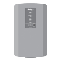
Details on 2 or 3-wire dampers, LEDs, and output terminals.
24 VAC input for panel; POWER LED behavior.
Humidifier and Electronic Air Cleaner relay control terminals.
Equipment LEDs, configuration settings, and time delay override.
Plenum sensor input and thermostat connection points.
Zone/Vacation and Emergency Heat selector switches.
Reminder to touch grounded metal object to prevent static discharge.
Wire count for different HVAC system types.
Wire count for Aprilaire thermostat models.
Recommended wire gauge and avoiding interference.
Mounting location guidelines to prevent condensation and ensure proper operation.
Configuration for Zone 1 specific or equal zone control operation.
Switch for heat pump vs. separate heating/cooling equipment.
Switch for electric heat control or gas/furnace heating system.
Setting for compressor fan purge delay after a call.
Sensor low limit for cooling and high limit for heating cutout.
Dip switch setting for staging based on number of zones or call duration.
Using the 2S terminal for thermostat-controlled staging.
Time settings for auxiliary heat activation based on thermostat or time control.
Note on thermostat control availability for auxiliary heat.
Instructions for wiring transformers for control panel and damper power.
Safety warning regarding 120-volt shock hazard during installation.
Table detailing thermostat requirements based on control panel settings.
Definitions for thermostat and control panel terminal labels.
Safety warning about disconnecting power before wiring HVAC equipment.
Schematics for single-stage and two-stage furnace/AC systems.
Wiring schematic for boiler and AC systems.
Wiring schematic for radiant floor/furnace/AC systems.
Schematics for single-stage and two-stage heat pump systems.
Definitions for heat pump and boiler terminal labels.
Wiring schematic for zone dampers to the control panel.
Check transformer phase before connecting multiple transformers.
Sensor mounting guidelines to avoid false readings.
Resistance values for the plenum sensor at different temperatures.
Wiring schematic for humidifier control and EAC.
Specific requirements for electronic air cleaner installation.
Wiring diagram for connecting Model 6402 expansion panels.
How the system switches between heating and cooling modes.
How temperature limits protect equipment from overheating/freezing.
Functionality of vacation and emergency heat selector switches.
Defines thermostat inputs for heat/cool systems.
Explains fan, heating cycle logic, and timing.
Detailed explanation of cooling cycle logic and timing.
Defines thermostat inputs and fan operation for Zone 1 controlled systems.
Heating and cooling operation logic when Zone 1 controls mode.
Defines thermostat inputs and fan operation for heat pump systems.
Heating, auxiliary, and cooling operation logic for heat pump systems.
Auxiliary heat controlled by thermostat settings or time delay.
Dual fuel effects and cooling cycle logic.
Operation of the emergency heat mode.
Defines thermostat inputs and fan operation for heat pump systems where Zone 1 sets mode.
Heating, auxiliary, dual fuel, and cooling logic for this mode.
Emergency heat operation in this specific heat pump mode.
| Brand | Aprilaire |
|---|---|
| Model | 6404 |
| Category | Controller |
| Language | English |