Do you have a question about the Aprilaire 8120 Series and is the answer not in the manual?
Electrical shock hazard from 120 volts and injury risk from sharp metal edges.
Installation notes on furnace blower operation and mounting placement.
Instructions for mounting the controller to the return ductwork.
Procedure for installing the controller mounting bracket on duct board.
Instructions for mounting the controller in a closet return plenum.
Procedure for installing the outdoor temperature sensor into the duct.
Instructions for wiring the controller to a furnace.
Instructions for wiring the controller to a heat pump.
Instructions for wiring to specific Aprilaire fresh air ventilators.
Instructions for wiring to the Model 8142NC fresh air ventilator.
Instructions for wiring to the Model 8144NC fresh air ventilator.
Instructions for wiring to the Model 6506 damper.
Select HP for heat pump or HC for furnace and AC wiring.
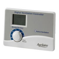
Input number of bedrooms to calculate ventilation rate.
Input square footage to calculate ventilation rate.
Enter measured outdoor airflow during ventilation.
Limit ventilation based on high outdoor temperature.
Limit ventilation based on low outdoor temperature.
Configure HVAC fan operation for ventilation and tempering.
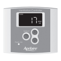
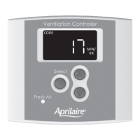
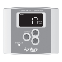
Select ventilation operation mode: CODE or COMFORT.
Set indoor humidity limits for ventilation control.
Steps to verify system function, wiring, and component operation.
Ventilation operation based on time cycles and temperature limits.
Ventilation operation based on temperature and humidity limits.
Instructions for registering the product's warranty online or by mail.
| Category | Controller |
|---|---|
| Zones Supported | Single Zone |
| Power Supply | 24 VAC |
| Voltage | 24 VAC |
| Wiring | 2-Wire |
| LCD | Yes |
| Humidity Control | Yes |
| Mounting | Wall Mount |
| Model | 8120 |
| Compatibility | Aprilaire Humidifiers |
| Operating Temperature Range | 32-120°F (0-49°C) |
| Dimensions | 4.5" H x 3" W x 1" D |