EasyManua.ls Logo

Aprilaire 8126 Series - User Manual

Aprilaire 8126 Series
11 pages
Print Icon
To Next Page IconTo Next Page
Loading...
MIN/
HR
CODE
READ AND SAVE THESE INSTRUCTIONS
Model 8120X Digital
Ventilation Controller
Installation and Operation Manual
Question and Answer IconNeed help?

Do you have a question about the Aprilaire 8126 Series and is the answer not in the manual?

Summary

Warnings and Cautions

General Safety Warnings

Electrical shock hazards and safe handling of sharp metal edges.

Installation Notices

Precautions for furnace blower operation and controller mounting location.

Package Contents

Included Components

Lists all items provided with the ventilation controller.

Specifications

Technical Specifications

Details operating temperature, load capacity, and input voltage.

Mounting Controller and Sensor

Mounting to 8140 NC Ventilator

Instructions for attaching the controller to the Model 8140NC ventilator.

Mounting to Return Ductwork

Sheet Metal Installation

Steps for mounting the controller onto sheet metal return ducts.

Duct Board Installation

Steps for mounting the controller onto duct board return plenums.

Mounting in Closet Return Plenum

Closet Mounting Procedure

How to mount the controller in a closet return plenum for accurate air sensing.

Mounting Outdoor Temperature Sensor

Sensor Installation Steps

Instructions for drilling and securing the outdoor temperature sensor into the duct.

Wiring the Ventilation Controller

Wiring to Furnace

Diagram and steps for connecting the controller to a furnace system.

Wiring to Heat Pump

Diagram and steps for connecting the controller to a heat pump system.

Wiring to 8140 NC Ventilator

Diagram and steps for connecting the controller to the 8140NC fresh air ventilator.

Wiring to Model 6506 Damper

Damper Connection Diagram

Wiring diagram for connecting to the Model 6506 damper.

Controller Operation

Display and Control Guide

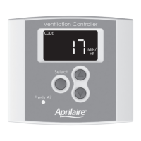
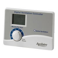
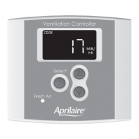
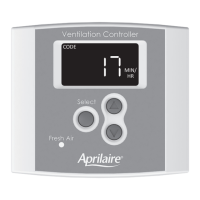
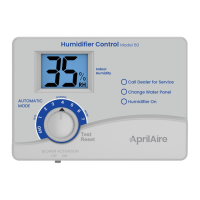
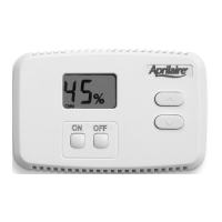
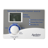
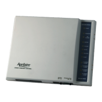
Explains the controller's display, buttons, and indicators during operation.

Set Up Menu Configuration

System Configuration Settings

Configure heat pump/furnace type, bedrooms, and square footage for ventilation.

Ventilation Temperature Limits

Set high and low temperature limits for ventilation control.

Fan Operation Settings

Configure how the HVAC fan interacts with ventilation (On, Blend, Off).

Set Up Menu Advanced Settings

Advanced Ventilation and RH Limits

Configure low fan temperature limit, mode, and indoor RH limits.

Test Mode Operation

System Verification Steps

Instructions to enter and understand the test mode for component verification.

Rater;Inspector Verification

CFM Verification Procedure

How to verify CFM settings against calculated values using formulas.

Sequence of Operation - Code Setting

Code Mode Ventilation Logic

Explains how ventilation operates under the 'Code' setting based on temperature.

Sequence of Operation - Comfort Setting

Comfort Mode Ventilation Logic

Explains how ventilation operates under 'Comfort' mode based on temperature and humidity.

Limited Warranty Information

Warranty Coverage Details

Details the five-year warranty for defects in materials and workmanship.

Warranty Registration

Product Registration Process

Instructions for registering the product online or by mail.

Overview

The Aprilaire Model 8120X Digital Ventilation Controller is a sophisticated device designed to manage and optimize fresh air ventilation in residential HVAC systems. It serves as the central control unit for various ventilation components, ensuring that homes receive adequate fresh air while maintaining indoor comfort and energy efficiency.

Function Description

The primary function of the Model 8120X is to provide continuous or intermittent fresh air ventilation based on user-defined settings and environmental conditions. It integrates with the home's existing HVAC system, including furnaces, heat pumps, and dedicated fresh air ventilators or dampers, to introduce outdoor air into the living space.

The controller operates in two main modes: "Code" and "Comfort."

  • "Code" Setting: This mode is designed to meet ventilation requirements as specified by ASHRAE 62.2-2010 standards. In this setting, the controller prioritizes meeting the calculated continuous ventilation rate. It will turn on ventilation during heating, cooling, or fan calls for a set number of minutes within a one-hour cycle. If the outdoor temperature exceeds a high limit, ventilation will not occur during cooling or fan calls but will proceed during heat calls if the temperature is below a low limit. If the HVAC equipment doesn't run long enough to meet the ventilation time within the hour, the controller will activate ventilation independently, turning on the HVAC system blower if configured to do so, provided outdoor air temperature is within limits. The system also features an adaptive cycle period, automatically adjusting from one-hour to four-hour, eight-hour, twelve-hour, and finally twenty-four-hour cycles if outdoor temperatures consistently fall outside the set limits. This ensures that missed ventilation time due to temperature extremes is made up, and total ventilation time increases in longer cycles to compensate for effectiveness as defined by ASHRAE standards. In the 24-hour cycle, ventilation will occur regardless of temperature limits to meet the requirements.
  • "Comfort" Setting: This mode focuses on balancing ventilation with indoor comfort, specifically considering indoor relative humidity (RH) levels in addition to outdoor temperature. Ventilation will occur during heating, cooling, or fan calls if both outdoor temperature and indoor RH are within their respective high and low limits. Similar to the "Code" setting, if the HVAC equipment doesn't run sufficiently to meet the ventilation time, the controller will initiate ventilation independently, activating the HVAC system blower if set up, as long as outdoor temperature and indoor RH are within the specified ranges. However, if either the outdoor temperature or indoor RH falls outside the set limits, ventilation will not occur in this mode, prioritizing comfort over strict code compliance for missed ventilation.

The controller calculates the required continuous ventilation rate based on the home's square footage and the number of bedrooms, allowing for precise control over fresh air intake. It also measures the actual outdoor airflow delivered during ventilation, ensuring accurate operation.

Usage Features

The Model 8120X features a user-friendly interface with a clear digital display and intuitive buttons for setup and operation.

  • Display: The display normally appears faint to conserve energy but illuminates at full power with the first button press. It shows the current ventilation time setting (in minutes per hour), the operating mode ("Code" or "Comfort"), and indicates whether the HVAC fan is active during ventilation.
  • Navigation and Selection: The "Select" button is central to navigating the Set Up Menu and confirming values. Up and down arrow buttons are used to adjust numerical settings.
  • Ventilation Time Override: Users can manually override the calculated ventilation time setting, adjusting it between 6 and 60 minutes per hour. A press and hold action on the override button can also turn ventilation OFF. To revert to the calculated setting, the user must go through the entire Set Up Menu.
  • Set Up Menu: This comprehensive menu allows users to configure various parameters:
    • HVAC System Type: Select between "HP" (heat pump) or "HC" (furnace and AC) to match the installed HVAC system.
    • Number of Bedrooms: Input the number of bedrooms, a factor in calculating the required continuous ventilation rate.
    • Square Footage: Enter the home's square footage, another key factor for ventilation rate calculation.
    • Measured Outdoor Airflow (CFM): Input the measured cubic feet per minute (CFM) of outdoor air delivered during ventilation. This value is crucial for accurate operation and must be determined before setup.
    • Ventilation High Temperature Limit: Set an upper temperature threshold for outdoor air. If the outdoor temperature exceeds this setting, ventilation will be limited. This can also be turned OFF if no high limit is desired.
    • Ventilation Low Temperature Limit: Set a lower temperature threshold for outdoor air. If the outdoor temperature falls below this setting, ventilation will be limited. This can also be turned OFF.
    • HVAC Fan Operation with Ventilation: Configure how the HVAC fan interacts with ventilation:
      • "On": The HVAC fan turns on whenever ventilation occurs.
      • "bLnd" (blend): The HVAC fan turns on with ventilation only when the outdoor temperature is within a set range, allowing for tempering of outdoor air with indoor air.
      • "OFF": The HVAC fan is not turned on with ventilation.
    • Blend Temperature Setting (available with "bLnd" fan setting): If "bLnd" is selected, this setting determines the outdoor temperature above which the HVAC fan will turn on to mix outdoor air with indoor air for tempering.
    • Operating Mode Selection: Choose between "code" (ASHRAE 62.2-2010 compliance) or "cFrt" (comfort-based ventilation with RH limits).
    • High Indoor RH Limit (available with "cFrt" mode): Set an upper indoor relative humidity threshold. If indoor RH exceeds this setting, ventilation will not occur.
    • Low Indoor RH Limit (available with "cFrt" mode): Set a lower indoor relative humidity threshold. If indoor RH drops below this setting, ventilation will not occur.
  • Test Mode: After wiring and setup, Test Mode can be activated by pressing and holding the "Select" button for 5 seconds. This mode allows for verification of all ventilation system components and HVAC fan wiring. It displays the outdoor temperature, activates the damper or power ventilator, and then turns on the HVAC fan if configured, providing a sequence of operational checks.
  • Rater/Inspector Verification: The controller allows for easy verification of the calculated Required Continuous CFM and the Measured CFM. This feature is useful for professionals to ensure the system meets design specifications.

Maintenance Features

The manual emphasizes the importance of proper installation and wiring for reliable operation, which is a key aspect of minimizing future maintenance needs. While the manual does not detail specific routine maintenance tasks for the controller itself, its design for integration with HVAC systems implies that general HVAC system maintenance would indirectly support the controller's performance. The robust construction and clear wiring diagrams contribute to a system that, once correctly installed, should require minimal direct maintenance. The "READ AND SAVE THESE INSTRUCTIONS" directive highlights the importance of retaining the manual for future reference, which would include troubleshooting or re-configuration if needed.

Aprilaire 8126 Series Specifications

General IconGeneral
ModelAprilaire 8126 Series
Voltage24 VAC
Wire Size18-22 AWG
Power Source24VAC Transformer
Humidity ControlAutomatic
Humidity Sensor Accuracy±5% RH
Weight0.5 lbs
MountingWall-mounted
Operating Temperature Range32°F to 122°F (0°C to 50°C)
Dimensions4.5" x 2.75" x 1.25" (114mm x 70mm x 32mm)

Related product manuals