EasyManua.ls Logo

Aprilaire 8145NC - User Manual

Aprilaire 8145NC
12 pages
Print Icon
To Next Page IconTo Next Page
Loading...
MODEL 8145 FRESH AIR VENTILATOR MODEL 8145NC FRESH AIR VENTILATOR
SAFETY INSTRUCTIONS
WARNING
1. 120 Volts may cause serious injury from electric shock. Disconnect electrical power before starting installation or servicing. Leave power
disconnected until installation/service is completed.
2. Sharp edges may cause serious injury from cuts. Use care when cutting plenum openings and handling duct work.
CAUTION
1. Read all instructions before beginning installation.
2. Improper installation may cause property damage or injury. Installation, service, and maintenance must be performed by a qualified service
technician.
READ AND SAVE THESE INSTRUCTIONS
VENTILATION CONTROLLER
FILTER
COVER
VENTILATION TERMINALSLOW PRESSURE
PORT
HIGH PRESSURE
PORT
INLET COLLAR AND
NORMALLY CLOSED
POWER DAMPER
OUTLET
COLLAR
SURFACE MOUNT
BRACKET LOCATION
JOIST MOUNT
BRACKET LOCATION
TABLE OF CONTENTS
Safety Instructions ...............................................1
Introduction and Compliance Statement ...........................2
Specifications ...................................................2
Install Electrical Outlet............................................2
Ventilator Location and Orientation................................3
Mount the Ventilator .............................................3
Mount Intake Hood ..............................................4
Install Ductwork .................................................4
Model 8145NC – Wiring to Various Controls.........................5
Model 8145NC – Test Mode .......................................6
Model 8145NC – Sequence of Operation............................6
Model 8145 – Wiring the Control to the HVAC System ...............6
Model 8145 – Connecting the Control to the Ventilator...............7
Model 8145 – Operation ..........................................7
Model 8145 – Test Mode ..........................................8
Measure Delivered Airflow ........................................8
Model 8145 – Set Up .............................................9
Model 8145 – Rater/Inspector Verification .........................10
Model 8145 – Sequence of Operation .............................10
Filter Cleaning...................................................11
Internal Schematics ..............................................11
Limited Warranty . . . . . . . . . . . . . . . . . . . . . . . . . . . . . . . . . . . . . . . . . . . . . . . 12
Model 8145 and 8145NC
Fresh Air Ventilator
Installation and Operating Instructions
10014353 B2208589A 4.20
English 1
Question and Answer IconNeed help?

Do you have a question about the Aprilaire 8145NC and is the answer not in the manual?

Summary

Safety Instructions

Warning Notices

Critical safety warnings regarding electrical shock and sharp edges.

Caution Notices

Precautions for proper installation and service by qualified technicians.

Introduction and Compliance

Compliance Standards

Lists standards met by the ventilators when properly installed.

Specifications and Dimensions

Performance Specifications

Details airflow and efficacy at different static pressures.

Unit Dimensions

Provides physical measurements of the ventilator.

Electrical Outlet Installation

Ventilator Location and Orientation

Mounting Clearance Requirements

Specifies minimum distances for safe operation and access.

Mounting Methods and Brackets

Explains how to attach the ventilator using provided brackets.

Intake Hood Installation

Ductwork Installation

Ducting Connections

Guides ducting from the intake hood to the unit and unit to HVAC system.

Model 8145 NC Wiring to Controls

Wiring to IAQ Control Module

Diagram for connecting to Aprilaire IAQ control models.

Wiring to Thermostat (8620;8620 W)

Diagram for connecting to specific Aprilaire thermostats.

Wiring to Digital Controller (8120 X)

Diagram for connecting to the Model 8120X controller.

Model 8145 NC Test Mode

Model 8145 NC Sequence of Operation

Model 8145 Wiring to HVAC System

Control Removal and Wiring Preparation

Steps to prepare and run wiring between control and HVAC.

Wiring to Furnace System

Wiring diagram for connecting to a furnace/AC system.

Model 8145 Wiring to Heat Pump

Connecting Control to Ventilator

Model 8145 Operation Overview

Control Display and Basic Functions

Explains the ventilator control display and button functions.

Model 8145 Test Mode Procedure

Measure Delivered Airflow

Airflow Measurement Technique

How to use a pressure gauge to measure airflow.

Airflow Conversion and Interpolation

Methods to convert pressure readings to CFM values.

Model 8145 Setup Menu

Navigating the Setup Menu

Instructions on using buttons to navigate setup options.

Setup Configuration Parameters

Details on setting ventilation, temperature, and humidity limits.

Model 8145 Verification

Rater;Inspector Verification Steps

Process for verifying settings against measured values.

Model 8145 Sequence of Operation

CODE Setting Operation Logic

Explains operation based on temperature limits and cycle periods.

COMFORT Setting Operation Logic

Explains operation considering temperature and humidity limits.

Filter Cleaning and Maintenance

Filter Cleaning Procedure

Step-by-step guide to clean the ventilator's filter.

Internal Schematics

Model 8145 Internal Schematic Diagram

Electrical schematic for the Model 8145 ventilator.

Model 8145 NC Internal Schematic

Limited Warranty and Registration

Warranty Terms and Conditions

Details the duration and exclusions of the product warranty.

Warranty Registration Process

Information on how to register the product for warranty coverage.

Overview

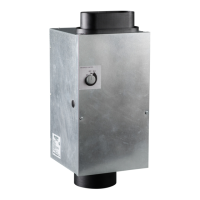
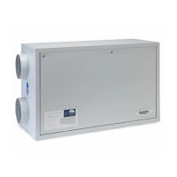
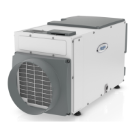
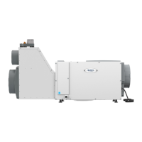
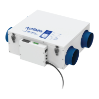
The Aprilaire Model 8145 and 8145NC Fresh Air Ventilators are designed to precisely introduce outdoor air into efficiently designed homes. These devices duct the inlet to an outdoor air intake and discharge to the HVAC system, providing mechanical ventilation that meets various standards such as Energy Star Certified Homes, EPA Indoor airPLUS, International Residential Code (IRC), International Energy Conservation Code (IECC), California Energy Commission Title 24, and ASHRAE Standard 62.2-2010, 2013, & 2016.

Function Description:

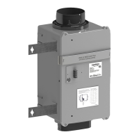
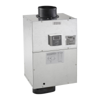
The ventilator's primary function is to bring in fresh outdoor air, filter it, and distribute it through the home's HVAC system. The Model 8145 includes an integral control for managing ventilation settings, while the Model 8145NC requires an external control. Both models feature an integral damper that opens when ventilation is active. The system can be configured to operate the HVAC blower during ventilation, either continuously or only when outdoor temperatures are within a set range (blend mode). Temperature and humidity limits can be set to prevent ventilation during extreme outdoor conditions, with options to make up for missed ventilation time (code setting) or prioritize comfort (cFrt setting).

Important Technical Specifications:

  • Airflow (CFM) and Efficacy (CFM/watt):
    • At 0.0 "w.c. external static pressure: 210 CFM, 5.2 CFM/watt
    • At 0.2 "w.c. external static pressure: 180 CFM, 4.4 CFM/watt
    • At 0.4 "w.c. external static pressure: 150 CFM, 3.5 CFM/watt
    • At 0.6 "w.c. external static pressure: 120 CFM, 2.8 CFM/watt
  • Voltage: 120 VAC, 1 phase, 60 Hz.
  • Dimensions:
    • Length: 23.41 inches (overall), 19.66 inches (main body)
    • Width: 13.01 inches
    • Height: 12.25 inches (overall), 13.906 inches (with mounting plate)
  • Duct Connections:
    • Inlet: Round collar for 6" diameter duct
    • Outlet: Oval collar for 6" diameter duct
  • Weight: Approximately 15 pounds.
  • Power Cord: 6-foot power cord with a standard 3-prong plug (NEMA 5-15).

Usage Features:

  • Control Options:
    • Model 8145: Features an integral control with a digital display for setting ventilation time (minutes/hr), mode of operation (Code or Comfort), and HVAC fan operation. It includes an on-board outdoor temperature sensor.
    • Model 8145NC: Requires external controls such as Aprilaire IAQ Control Models (8910, 8910W, 8920W), Aprilaire Thermostat Models (8620, 8620W), or Aprilaire Model 8120X Digital Ventilation Controller. An outdoor temperature sensor may be required for these external controls to use outdoor temperature limits.
  • Ventilation Settings:
    • Required Continuous CFM Calculation: Based on floor area (ft²) and number of bedrooms.
    • Ventilation Time Setting: Calculated as (Required Continuous CFM / Measured CFM) * 60 minutes per hour.
    • Temperature Limits: High and low outdoor temperature limits can be set to prevent ventilation during extreme conditions.
    • Humidity Limits (cFrt mode only): High and low outdoor RH limits can be set to prevent ventilation during high or low humidity conditions.
    • HVAC Fan Operation: Can be set to ON (always runs with ventilation), bLnd (runs only when outdoor temperature is outside a set range for tempering), or OFF (HVAC fan does not run with ventilation).
  • Test Mode: Allows verification of ventilator operation, damper opening, HVAC blower activation, and measurement of delivered airflow.
  • Rater/Inspector Verification: Allows display of calculated Required Continuous CFM and Measured CFM to verify settings.
  • Sequence of Operation:
    • "CODE" Setting: Ventilation occurs for the set minutes during a one-hour cycle. If outdoor temperature exceeds limits, ventilation is skipped but made up in subsequent cycles (adjusting to 4, 8, 12, or 24-hour cycles). HVAC blower turns on if wired and set up.
    • "COMFORT" Setting: Ventilation occurs for the set minutes during a one-hour cycle, but only if outdoor temperature and RH are within set limits. Missed ventilation due to limits is not made up. HVAC blower turns on if wired and set up.

Maintenance Features:

  • Filter Cleaning: The fresh air filter should be removed and cleaned every six months, with an initial check after three months to determine optimal frequency. To clean, flex the outside edges of the filter door to disengage it, lift the door, remove the filter, rinse with water, shake off excess moisture, and replace.
  • Intake Hood Screen Cleaning: The screen at the fresh air intake hood on the outside of the house should also be cleaned regularly, as a clogged screen is a common cause of reduced ventilation.
  • Service Access: Requires 12 inches of filter access and 24 inches of fan access for servicing.
  • Installation: Can be mounted in any orientation (wall, hanging from joists, between floor joists, surface mount) using provided brackets and screws. Ductwork requires 6" insulated flexible duct. Electrical installation requires a standard NEMA 5-15 receptacle.

Aprilaire 8145NC Specifications

General IconGeneral
BrandAprilaire
Model8145NC
CategoryFan
LanguageEnglish

Related product manuals