EasyManua.ls Logo

Aprimatic ZT44 User Manual

Aprimatic ZT44
62 pages
Go to English
To Next Page IconTo Next Page
Page #1 background imageLoading...
Page #1 background image
Ce manuel a été réalisé par le constructeur et fait partie intégrante du produit.
Il contient toutes les informations nécessaires pour:
sensibiliser les installateurs aux problèmes liés à la sécurité;
installer le dispositif de manière correcte;
connaître le fonctionnement et les limites du dispositif;
utiliser correctement le dispositif dans des conditions de sécurité optimales.
Le respect des indications fournies dans ce manuel garantit la sécurité personnelle, une économie de
fonctionnement et une longue durée de vie du produit.
Afi n d’éviter des opérations incorrectes et de ne pas risquer des accidents sérieux, lire attentivement ce manuel
et respecter scrupuleusement les informations fournies.
Les instructions, les dessins, les photos et la documentation contenus dans ce manuel sont la propriété de la société
APRIMATIC S.p.a et ne peuvent être reproduits sous aucune forme, ni intégralement, ni partiellement.
BUT DU MANUEL
Este manual ha sido redactado por el constructor y forma parte integrante del producto.
Contiene todas las informaciones necesarias para:
la correcta sensibilización de los instaladores hacia los problemas de la seguridad;
la correcta instalación del dispositivo;
el conocimiento en profundidad de su funcionamiento y de sus límites;
el correcto uso en condiciones de seguridad;
La constante observación de las indicaciones suministradas en este manual, garantiza la seguridad del hombre, la
economía del ejercicio y una mayor duración de funcionamiento del producto.
Con el n de evitar maniobras equivocadas con riesgo de accidente, es importante leer atentamente este manual,
respetando escrupulosamente las informaciones suministradas.
Las instrucciones, los dibujos, las fotografías y la documentación que contiene este manual son propiedad de
APRIMATIC S.p.a y no pueden ser reproducidas en ninguna manera, ni integral ni parcialmente.
OBJETO DEL MANUAL
Dieses Handbuch wurde vom Hersteller verfasst und ist ein ergänzender Bestandteil des Produkts.
Es enthält alle nötigen Informationen für:
die richtige Sensibilisierung der Monteure für Fragen der Sicherheit;
die vorschriftsmäßige Installation der Vorrichtung;
die umfassende Kenntnis ihrer Funktionsweise und ihrer Grenzen;
die vorschriftsmäßige und sichere Benutzung.
Die ständige Beachtung der in diesem Handbuch gelieferten Hinweise gewährleistet die Sicherheit der Personen,
wirtschaftlichen Betrieb und eine lange Lebensdauer des Produkts.
Zur Vermeidung fehlerhafter Manöver mit Unfallgefahr ist es wichtig, dieses Handbuch aufmerksam durchzulesen
und die darin enthaltenen Informationen genauestens zu beachten.
Die Anleitungen, Zeichnungen, Fotos und Dokumentationen in diesem Handbuch sind Eigentum von APRIMATIC
S.p.a. und dürfen in keiner Weise ganz oder teilweise reproduziert werden.
ZWECK DES HANDBUCHS
This manual was drawn up by the manufacturer and is integral part of the product.
It contains any useful information:
to draw the attention of the installers to safety related problems;
to install the device properly;
to know its operation and limits in depth;
to use the device under safe conditions.
The strict observance of the instructions of this manual grants safety conditions as well as
effi cient operation and a long life to the product.
To prevent operations that may result in accidents, read this manual and strictly obey
the instructions provided.
Instructions, drawings, photos and literature contained herein are exclusive property of
APRIMATIC S.p.A. and cannot be reproduced by any means.
PURPOSE OF THE MANUAL
ZT42 - ZT44
Istruzioni per l’installazione
Installation instructions
Instructions pour l’installation
Installationsanleitung
Instrucciones para la instalación
Questo manuale è stato redatto dal costruttore ed è parte integrante del prodotto.
In esso sono contenute tutte le informazioni necessarie per:
• la corretta sensibilizzazione degli installatori alle problematiche della sicurezza;
• la corretta installazione del dispositivo;
• la conoscenza approfondita del suo funzionamento e dei suoi limiti;
• il corretto uso in condizioni di sicurezza;
La costante osservanza delle indicazioni fornite in questo manuale, garantisce la sicurezza dell’uomo, l’economia
di esercizio ed una più lunga durata di funzionamento del prodotto.
Al ne di evitare manovre errate con il rischio di incidenti, è importante leggere attentamente questo manuale,
rispettando scrupolosamente le informazioni fornite.
Le istruzioni, i disegni, le fotografi e e la documentazione contenuti nel presente manuale sono di proprietà
APRIMATIC S.p.a e non possono essere riprodotti in alcun modo, né integralmente, né parzialmente.
SCOPO DEL MANUALE
Italiano
EnglishFrançais
Deutsch
Cod. A5304000 rev. 01 10/2001
AP030
Il logotipo "Aprimatic" è un marchio registrato di APRIMATIC S.p.A. Stampato in Italia.
The logo "Aprimatic" is a trademark registered by APRIMATIC S.p.A.
Le logotype "Aprimatic" est une marque déposée d'APRIMATIC S.p.A.
Das Logo "Aprimatic" ist ein eingetragenes Warenzeichen der APRIMATIC S.p.A.
El logotipo "Aprimatic" es una marca registrada de APRIMATIC S.p.A.
Espanish

Table of Contents

Question and Answer IconNeed help?

Do you have a question about the Aprimatic ZT44 and is the answer not in the manual?

Aprimatic ZT44 Specifications

General IconGeneral
Motor voltage24 Vdc
Protection levelIP44
Power Consumption120 W
Power supply230V AC
Safety FeaturesObstacle detection

Summary

1 Characteristics

1.2 Choosing the type of automation

Deciding the correct hydraulic operator version based on gate characteristics and dimensions.

1.3 General characteristics

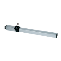
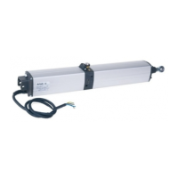
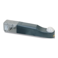
Overview of the ZT 44 hydraulic operator for residential swing gates, including versions and features.

2 Preliminary operations

2.1 Preliminary checks

Essential checks on gate leaves, hinges, and structure before installation to ensure proper operation.

2.2 Checking the operator components

Verifying the operator model code and ensuring all listed components are present and undamaged.

2.3 Preparing the mounting

Listing essential preparatory on-site jobs and required tools for independent installer work.

2.4 Components layout

Diagram and list of all operator components and optional safety devices for gate automation.

2.5 Electrical connections

Guidance on making electrical connections according to wiring diagrams and safety regulations.

3 Installation

3.1 Positioning of mountings

Recommended data for fixing operator mountings relative to gate leaf rotation center.

3.2 Preparing the rear mounting

Steps for preparing rear operator mounting on iron or masonry posts, including strengthening plates.

3.2.1 Preparations for rear operator mounting on iron posts

Detailed steps for preparing rear operator mounting on iron posts, focusing on cleaning welding zones.

3.2.2 Preparations for rear operator mounting on masonry posts

Methods for mounting operators on masonry posts using plates with hooked fittings or stud bolts.

3.2.3 Preparations for rear operator mounting on masonry posts with inset

Instructions for preparing masonry posts with insets for rear operator mounting, detailing measurements.

REAR OPERATOR MOUNTING - SPECIAL CASES

Specific mounting modifications for outward-opening gate leaves using an L-plate.

REAR OPERATOR MOUNTING

Procedure for rear operator mounting on iron posts and masonry posts with prepared insets.

3.3 Fitting the rear anchorage plates

Detailed steps for fitting rear anchorage plates using expansion plugs or glue fitting methods.

3.4 Fitting the rear operator mounting

Instructions for positioning and welding the rear operator mounting to the anchorage plate.

3.5 Positioning the front mounting

Steps for spreading grease, fitting the ball joint, and attaching the fork to the operator for front mounting.

3.6 Temporary rear fitting of the operator

Procedure for temporarily fitting the operator to the mounting using vibration damper bushings and a vertical pin.

3.7 Frontal positioning of the operator

Using a template to correctly position the operator's front mounting for maximum rod stroke length.

3.8 Final fitting of the operator

Steps for greasing, fitting the jointed head, and securing the operator to the rear mounting.

3.9 Final assembly

Includes bleeding the operator and adjusting the brake in the close position.

3.9.1 Bleeding

Procedure to bleed the operator by cycling the stroke end and acting on the screw to remove air.

3.9.2 Adjusting the brake in close position

Guide for adjusting the hydraulic brake setting screw for smooth slowdown during closing.

3.9.3 Slowing down the operator opening

Instructions for enabling opening slowdown function, specific to ZT44 SF DS version.

3.9.4 Final assembly

Fitting protective casings, push-on cover, and tightening screws for final assembly.

4 Finals operations

4.1 Checks and settings

Measuring thrust force, adjusting control valves for opening and closing, and performing final checks.

5 Notes for the user

5.1 Emergency operation - use of manual release

Procedure for accessing and using the manual release key for emergency gate operation.

5.2 Notes for the installer

Important notes and maintenance recommendations for installers.

5.2.1 Maintenance

Regular maintenance tasks including greasing, checking structure, safety devices, and oil level.

5.2.2 Trouble-shooting guide

Guide to identify and resolve common faults and probable causes in operator operation.

Related product manuals