EasyManua.ls Logo

Aprimatic ZT42 (B-SR) - User Manual

Aprimatic ZT42 (B-SR)
14 pages
Print Icon
To Next Page IconTo Next Page
Loading...
- 14 -
English
AP030
R
Characteristics
1
1.1 Technical data ........................................................................................................................................................................................... 14
1.2 Choosing the type of automation .............................................................................................................................................................. 15
1.3 General characteristics ............................................................................................................................................................................. 15
Preliminary operations
2
2.1 Preliminary checks.................................................................................................................................................................................... 15
2.2 Checking the operator components .......................................................................................................................................................... 16
2.2.1 List of components (B4) ............................................................................................................................................................................ 16
2.3 Preparing the mounting............................................................................................................................................................................. 16
2.4 Components layout (B2) ........................................................................................................................................................................... 17
2.5 Electrical connections ............................................................................................................................................................................... 17
3
3.1 Positioning of mountings ........................................................................................................................................................................... 18
3.2 Preparing the rear mounting ..................................................................................................................................................................... 18
3.2.1 Preparations for rear operator mounting on iron posts ............................................................................................................................. 18
3.2.2 Preparations for rear operator mountings on masonry posts.................................................................................................................... 19
3.2.3 Preparations for rear operator mounting on masonry posts with inset...................................................................................................... 19
3.3 Fitting the rear anchorage plates .............................................................................................................................................................. 20
3.4 Fitting the rear operator mounting............................................................................................................................................................. 20
3.5 Positioning the front mounting................................................................................................................................................................... 20
3.6 Temporary rear fi tting of the operator........................................................................................................................................................ 21
3.7 Frontal positioning of the operator ............................................................................................................................................................ 21
3.8 Final fi tting of the operator ........................................................................................................................................................................ 22
3.9 Final assembly .......................................................................................................................................................................................... 22
3.9.1 Bleeding .................................................................................................................................................................................................... 22
3.9.2 Adjusting the brake in close position......................................................................................................................................................... 22
3.9.3 Slowing down the operator opening (C29)................................................................................................................................................ 23
3.9.4 Final assembly .......................................................................................................................................................................................... 23
Finals operations
4
4.1 Checks and setting.................................................................................................................................................................................... 24
5
5.1 Emergency operation - useof manual release .......................................................................................................................................... 25
5.2 Notes for the installer ................................................................................................................................................................................ 25
5.2.1 Maintenance ............................................................................................................................................................................................. 25
5.2.2 Trouble-shooting guide.............................................................................................................................................................................. 25
1.1 TECHNICAL DATA
Installation
Notes for the user
Index / Characteristics
Warning
!
The noise level of the above models, with reference to the working of the operator independently of the gate leaf and the gate post,
falls within the maximum limits set by EEC standards.
230 V±10% 50 Hz
230 V±10% 50 Hz
ZT44 ABC ZT44 SF DS
CHARACTERISTICS
Single-phase system voltage
Power absorption
Mean pressure
Thrust force at 10 bar
Traction force at 15 bar
Rod return time (complete stroke)
Rod advance time
Max leaf length
Min leaf length
Operating temperature range
Max distance between centres for mounting holes
with fully extended rod
Max stroke - standard arm
Weight with oil
Oil quantity
Oil type
250W 250W
962 N
30 bar
30 bar
1140 N
-20˚ / + 70˚C
1002 mm
± 5
270 mm
8 Kg
0,6 lt.
Aprimatic Oil HC13
ZT42 (B-SR)
230 V±10% 50 Hz
250W
30 bar
962 N
962 N
1140 N 1140 N
12,5 sec 17,5 sec 17,5 sec
15,5 sec 21,5 sec
21,5 sec
1,2 m 1,8 m
4 m
0,8 m 1,2 m
1,2 m
-20˚ / + 70˚C
-20˚ / + 70˚C
1002 mm
± 5
1002 mm
± 5
190 mm
270 mm
8 Kg
8 Kg
0,6 lt.
0,6 lt.
Aprimatic Oil HC13
Aprimatic Oil HC13
Protection degree
IP 55 IP 55 IP 55
Question and Answer IconNeed help?

Do you have a question about the Aprimatic ZT42 (B-SR) and is the answer not in the manual?

Overview

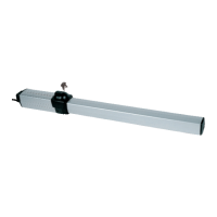
The Aprimatic ZT 44 is a hydraulic operator specifically designed for swing gates, primarily for residential use. Its main function is to automate the opening and closing of gates, providing a reliable and efficient solution for gate access. The device is available in various versions, each offering distinct features to suit different gate types and operational requirements.

Function Description

The core function of the ZT 44 operator is to provide automated movement for swing gates. It utilizes a hydraulic system to extend and retract a rod, which in turn pushes and pulls the gate leaf. The hydraulic mechanism ensures smooth and controlled gate movement.

One of the key features is the flow adjustment system, which allows for balancing and regulating the irregular speed of the gate. This is particularly useful when the gate experiences varying loads due to factors like an uneven gate, friction in hinges, or wind. By adjusting valves A and B, the intensity of the flow adjustment can be increased or decreased. Turning both valves clockwise reduces the gate speed, while turning them anti-clockwise disables the flow adjustment, allowing for standard functioning. It is crucial to adjust both valves to the same intensity (A=B) for optimal performance.

The ZT 44 also incorporates different locking mechanisms depending on the version:

  • A version: Hydraulic lock for opening only.
  • B version: Double hydraulic lock for both opening and closing.
  • C version: Hydraulic lock for closing only, with the lock inaccessible when the gate is open. This version is not recommended for gate leaves exceeding 1.8 meters in length.
  • SF version: No hydraulic lock, but includes a braking action. The gate leaf can be moved manually with minimal resistance when moved slowly. It also features a release device to facilitate opening, requiring an electric lock for use in windy zones.
  • SR version: Similar to the SF version, with no hydraulic lock and a braking action, allowing manual movement with minimal resistance. It also includes a release device for opening, requiring an electric lock for use in windy zones.

An emergency release mechanism is integrated into the operator, allowing for manual control of the gate in the event of a power outage. This feature is accessed via a personalized key through an opening compartment on the upper cover of the operator, designed for ease of use and maneuverability.

The device also includes a "non-crush" safety feature, implemented through sensitive valves that can be set during installation. This enhances safety by preventing excessive force during gate operation.

Usage Features

Proper installation and adjustment are critical for the optimal functioning and safety of the ZT 44 operator. Before installation, it is essential to select the appropriate type of automation based on the gate's characteristics and dimensions. The ZT 44 is designed to conform to UNI 8612 safety standards when installed correctly.

The peripheral speed of the gate leaf must always be less than 12 m/min to comply with UNI 8612 regulations. High-speed operators should be avoided on wide gate leaves to prevent violent banging against the gate stop.

Mounting the operator involves several steps, starting with preparing the rear and front mountings. The rear mounting can be adapted for both iron and masonry posts. For masonry posts, specific insets and anchorage plates are required, with precise measurements to ensure stability. Welding is often involved in securing the mountings, and it is crucial to protect components like bushings and the rod from welding residue and sparks.

The front mounting involves fitting the ball joint to the threaded stem and then attaching the operator arm. Abundant greasing of pins and housings is recommended during this process.

Temporary rear fitting of the operator involves securing it with vibration damper bushings and a vertical pin, ensuring careful handling during assembly.

Frontal positioning of the operator often utilizes a template to achieve the maximum useful length of the rod. This involves releasing the operator manually, fully extending the rod to a specific length (285 mm for the ZT 44), and then retracting it slightly (5 cm) before securing the front mounting. The welding zone for the front mounting must be clean, and the rod and ball joint must be protected during welding.

After mounting, the hydraulic lock (if present) must be neutralized by turning the release key anti-clockwise. The gate leaves should then be moved manually and slowly to check for smooth movement without rubbing or interference. Once checks are complete, the hydraulic lock is reset by turning the release key clockwise.

Bleeding the operator is a crucial step before final adjustments. This involves operating the gate multiple times to stroke end (open or close position) and manipulating a specific screw to lock and release the operator, ensuring air is expelled from the hydraulic system.

Adjusting the brake in the close position is another important usage feature. The operator is supplied with a cut-out brake. To adjust it, the rod is retracted, the slow-down setting screw is tightened clockwise, and the operator is powered to close for a longer duration than necessary. Then, the slow-down setting screw is rotated counter-clockwise slowly for a maximum of four complete turns until the rod starts moving again. Final adjustments are made by rotating the screw by half a turn as needed. It is important not to unscrew the hydraulic brake setting screw completely to prevent oil leakage.

Slowing down the operator opening (specific to the ZT44 SF DS version) requires using the entire stroke length of the rod. In this version, 12 mm of the rod will protrude when fully withdrawn.

Final assembly includes fitting protective casings and covers, tightening fixing screws, and removing the bleed screw. A single drop of hydraulic oil from the duct created by removing the bleed screw is considered normal. If necessary, a protective sheath should be fitted to the power supply cable.

Maintenance Features

Regular maintenance is essential to ensure the longevity and proper functioning of the Aprimatic ZT 44 operator. All maintenance tasks should be performed by skilled technicians.

Before any maintenance job, the operator must be turned off by means of the differential switch of the electric system to ensure safety.

Key maintenance activities include:

  • Greasing: Joints should be greased with graphitized grease annually.
  • Structural Checks: The general condition of the gate structure, including the mechanical resistance of hinges, operator mountings, and stops, should be checked regularly.
  • Safety Device Checks: All installed safety devices, such as photocells and rubber barriers, must be checked to ensure they are in working order.
  • Thrust Force Adjustment: The thrust force at the end of the gate leaf should be adjusted to a maximum of 147 N (15 kg). The opening thrust should be set slightly higher than the closing thrust. After adjustments, the thrust force must be re-checked with a dynamometer. If the gate requires excessively high pressure to move, a thorough check of mechanical parts, plumb, and free movement of the gate leaf is necessary.
  • Electrical System Checks: The efficiency of the electrical system and the differential switch should be verified.
  • Pressure Relief Valve: The setting of the pressure relief valve should be checked.
  • Safety Lock: The tightening of the safety lock needs to be checked.
  • Oil Level: Depending on the operator's usage, the oil level in the system should be checked.
  • Emergency Release: The proper functioning of the manual emergency release mechanism should be checked periodically, at least every 12 months.

Troubleshooting guidance is provided for common issues. For example, if the motor does not run, checks include power supply, fuses, and cable damage. If the motor runs but the leaf does not move, checks involve the hydraulic release valve setting and opening pressure. If the operator jerks during motion, it may indicate air in the cylinder, insufficient oil, or incorrectly fitted mountings, requiring bleeding, adding oil, or repairing mountings respectively.

Aprimatic ZT42 (B-SR) Specifications

General IconGeneral
BrandAprimatic
ModelZT42 (B-SR)
CategoryGate Opener
LanguageEnglish

Related product manuals