AquaMaster
®
Owner’s Manual 1/21/2021 27
Assembly and Parts, Cont.
Drain End Cap Assembly
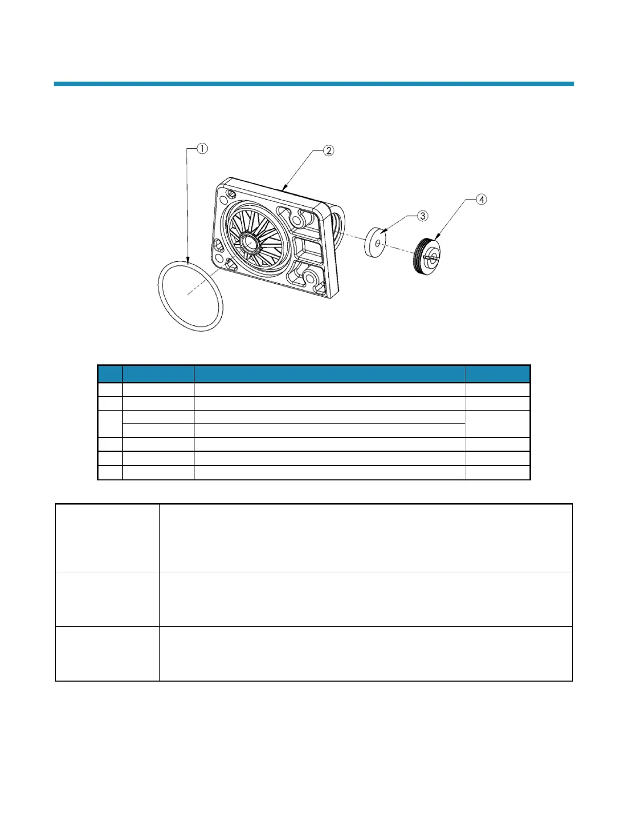
Figure 17: Drain End Cap Assembly
Drain Line Flow Control— Models 5000 and 5100
Drain Line Flow Control— Model 5500
Entire Assembly (all the above parts)—Models 5000 and 5100
Entire Assembly (all the above parts)—Model 5500
Cap
The Drain End Cap (90268) seals the left opening on the Main Valve Body. The opening is sealed
with an O-Ring used as axial or “face” seal. The O-Ring sits in a groove in the End Cap. This
groove must be free of defects such as pits or scratches and also free of debris. When
assembling the End Cap to the Valve Body, care should be taken to make sure that the O-Ring
stays in the groove in the End Cap. If misaligned, the O-Ring can become pinched and leak.
Flow Control
The Drain Line Flow Control (DLFC) maintains a constant (plus or minus 10%) backwash flow rate
at varying pressures. Care should be taken when replacing DLFCs to ensure that the correct rate
is being used for a particular model. Refer to Specifications. When assembling the flow control,
ensure that the rounded (radiused) side of the hole faces in toward the water flow.
The Retainer (90267) holds the backwash Flow Control (H2086) in place. One side is smooth and
the other has a groove for a screwdriver. When assembling the retainer to the Drain End Cap
(90268), the retainer should be screwed in until it stops. If the retainer is not fully engaged, the
Flow Control may not function properly.