Model 25A250B
8 Rev A
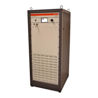
Figure 2-2. Model 25A250B Rear Panel
2.3 LOCAL OPERATION
2.3.1 Power-up Sequence
1. Connect the input signal to the unit’s RF INPUT connector. The input signal level should be 0dBm
maximum.
2. Connect the load to the unit’s RF OUTPUT connector.
3. Set the REMOTE/LOCAL switch to LOCAL.
4. Check to see that the MAIN POWER switch on the unit’s rear panel is set to the 1 (on) position.
5. Press the POWER switch: the front panel vacuum fluorescent display (VFD) should read POWER ON,
when power is applied.
NOTE: The amplifier changes state each time the POWER switch is depressed—if the unit is on
when the POWER switch is depressed, it will turn off; if the unit is off when the POWER
switch is depressed, it will turn on.
6. Adjust the amplifier’s gain by rotating the GAIN knob.
7. In the event of a fault, press the FAULT/RESET switch; if the fault does not clear, refer to subsection 4.3
Troubleshooting of this manual.