PL7004 Kit
Rev F 17
source. Spatial variations occur in close proximity to a radiating antenna creating a test field or in a GTEM
with expanding dimensions, causing noticeable field changes with propagation distance. Caution should be
exercised in the use of the composite measurement of isotropic probes when there is significant spatial
variation in the field over the dimensions the probe. Repositioning the probe to adjust for the individual offset
of each axis may produce a more consistent result.
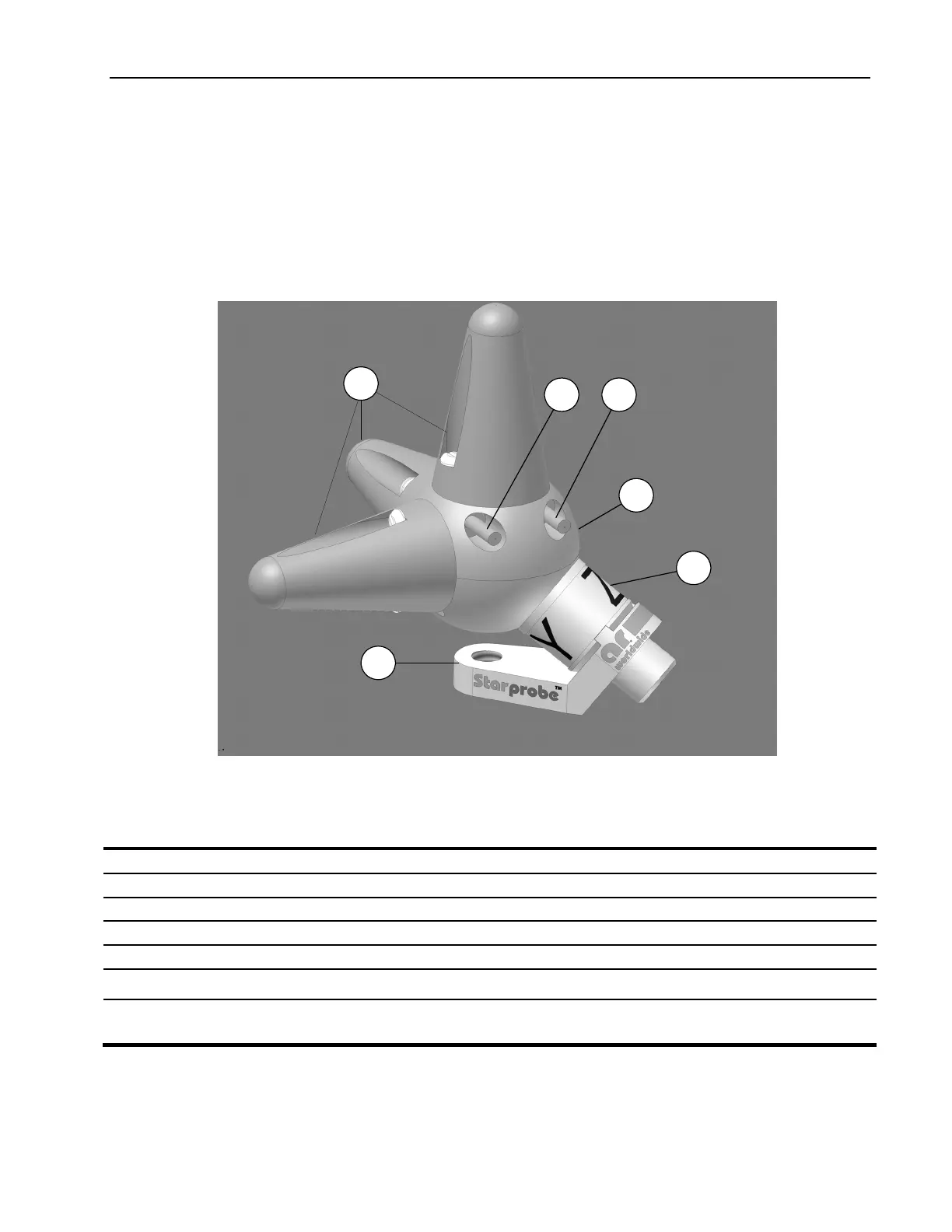
3.4 PROBE KIT APPEARANCE AND FEATURES
3.4.1 PL7004 Probe
1,2
3
4 5
6
7
Figure 3-1: PL7004 Probe Features
Table 3-1. PL7004 Probe Features
Label Title Function
1 Sensor elements Three antennas sensor elements to sense electric field. Each includes one diode detector.
2 Radomes Protects and supports the sensors
3 Housing Protects and shields the probe electronic components
4 Fiber Optic Cable L Routes laser (optical) power and commands to probe
5 Fiber Optic Cable X Routes (optical) transmit data from probe
6 Probe Base Provides mount via ¼ -20 screw. Rotation about screw axis brings each sensor through the
same position.
7 Mounting Adapter For mounting probe with a selected sensor axis aligned to a mounting screw axis. This is the
normal mounting position when the probe is used to measure individual field axis (X,Y,Z)
components.