PL7004 Kit
18 Rev F
3.4.2 Probe Interface
The Power switch on the interface activates the interface (ON) and deactivates the interface and probe (OFF).
A separate key on the interface enables the laser. A momentary switch initiates the laser on sequence. If the
fiber optic cables are not sensed or the probe does not respond within a preset time – as would be the case if
the interconnecting fiber optic cables are not fully installed or damaged - the laser is turned off as a safety
precaution.
Front panel indicators show that the AC power is applied, when the interface’s laser is on, F/O cable
connection status and that the probe is responding.
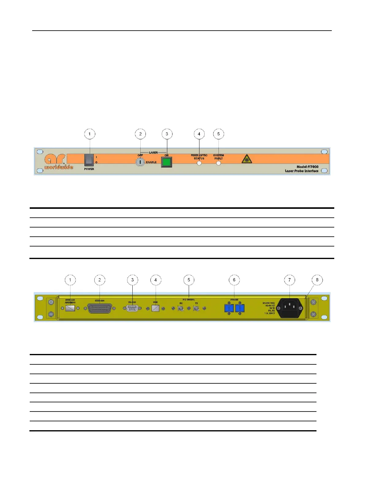
Figure 3-2: Interface Assembly Front Panel Features
Table 3-2 Interface Assembly Front Panel Features
Turns on the probe kit and illuminates to indicate that prime power is applied.
Enables the laser power supply.
Illuminated momentary switch to start laser on sequence. Switch is illuminated when laser is on.
Illuminates Green when F/O connection is sensed. Illuminates Red if cable fault is present.
Illuminates Red if probe communication is terminated and F/O cable is still sensed. Off indicates
safe condition (no faults).
Figure 3-3. Probe Interface Assembly Rear Panel Features
Table 3-3. Probe Interface Assembly Rear Panel Features
Sets device address for GPIB communication
GPIB (IEEE-488) Connector
Universal Serial buss connector to host
F/O Serial for connection to FM7004
Protects and shields the electronic components