H
I
H1
H2
H3
J
L
Phillips Screw Driver
Phillips Flat Head Bolt - 4 pcs
Panel Bolt - 4 pcs
Panel Bolt Lock - 4 pcs
Upper Section Bottom Panel - 1 pc
Upper Panel - 1 pc
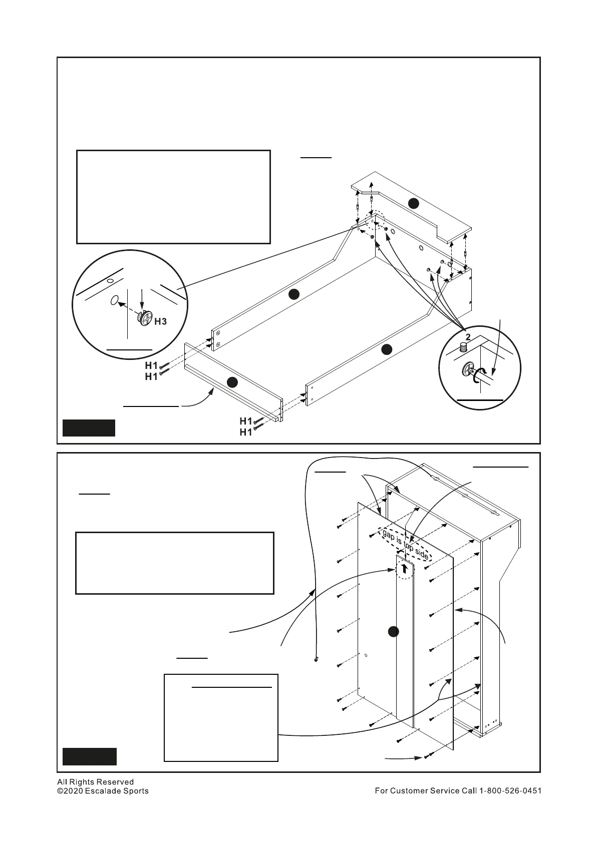
Install Part J to Part H and Part I using H1 Phillips Flat Head Bolts. See Figure 9.
Tighten, but do Not over tighten or strip out H1 Bolts.
Screw 4 pcs H2 Panel Bolts into factory preinstalled plastic inserts on Part L.
Tighten, but do Not over tighten or strip out H2 Bolts.
Insert 4 pcs H3 Panel Locks into holes on Parts H and I. Make sure the opening on the H3 Panel Bolt
Locks point upward. See Figure 9A.
Install Part L to Parts H and I. Tighten H3 Panel Bolt Locks with a Phillips Screwdirver. See Figure 9B.
15.
16.
17.
18.
Attach Part N to back of Upper Cabinet assembly
using H8 Phillips Round Head Screws.
NOTE: “Arrow UP” is face up.
See Figure 10.
Tighten, but do Not over tighten or strip out
H8 Screws.
19.
N
H8
N
Phillips Screw Driver
Phillips Round Head Screw - 20 pcs
Upper Back Panel - 1 pc
J
L
H2
H3
H3
H3
H3
H2
H2
H2
Opening
must face
upward
Figure 9A
Phillips
Screwdriver
NOTE: “Arrow UP” is face up
NOTE: Must be flush
NOTE: Part L must set down flush with Parts H
and I before tightening H3 Bolt Locks
Figure 9B
PARTS REQUIRED
PARTS REQUIRED
Important NOTE:
Make sure edge of top,
left and right sides are
flush with upper and
side cabinet edges.
Make sure NO gaps at
right, left & top side.
Important !!
Lip to bottom side
Laminate
to inside
11
Figure 9
Figure 10
LED wire on this side
Important !!
Gap must be
on top side
All screws are H8