8
3 INSTALLATION
3.1 Safety regulations
• Do not install the control unit inside the driver’s cab.
• Install unit so that manual valves can be easily accessed, but well away from opera-
tor’s station.
• The intake ow rate for the unit must be less than maximum ow rate envisaged for
the main control valve.
• The parts and the hoses that are installed on the main pressure line (delivery line)
must be capable of withstanding greater levels of pressure than that of the maximum
pressure valve (refer to Par. 7.1 - Correspondence between valve parts and maximum
valve pressure).
• Commission the drainage system according to the maximum delivery ow rate for
the pump. Also install hose whose nominal operating pressure is greater than that
of the drain: any bottlenecks in the drainage system could cause abnormally high
pressure levels.
• Make sure the hoses used are suitable for the diameters of the chosen hose tails.
Use systems to secure the hoses that are suitable for the hoses in question.
• It is recommended to install a pressure-relief device (Series 459 on general ARAG
catalogue) on the pump to avoid risks caused by a unit malfunction.
This device does not replace a further safety valve, but it can limit unit damages in
case of sudden over-pressures.
Contact skilled personnel for any intervention requiring modications to the congu-
ration of the hydraulic connections.
ARAG is not liable for any damage to equipment or injury to persons, animals or
things caused by incorrect or unsuitable connection of the unit.
Likewise, ARAG is not liable for any damage caused directly or indirectly to
equipment or machinery, or injury to persons, animals or things caused by unsuita-
ble or unt hoses, cable grips, wraps or other accessory.
All forms of warranty are rendered null and void in case of damage to the unit caused
by the abovea.
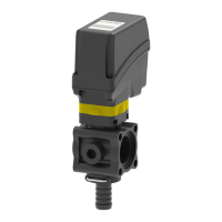
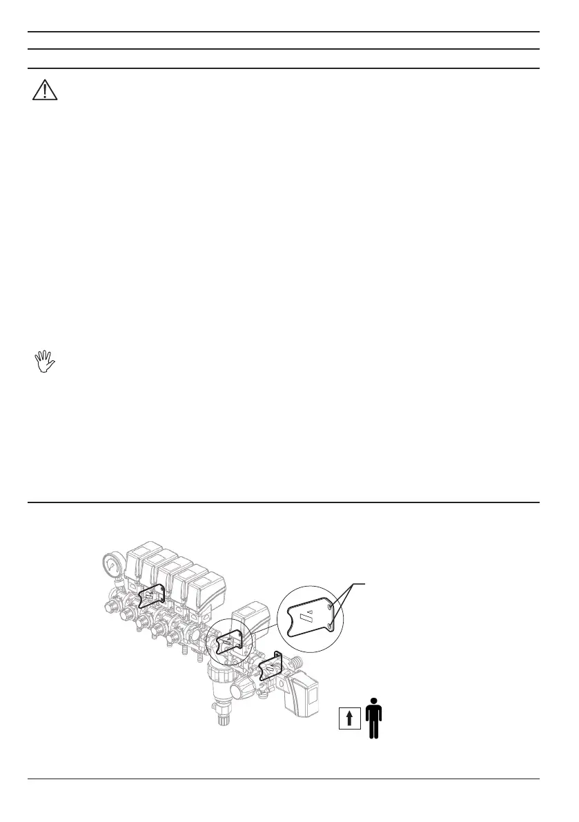
3.2 Installing and connecting the unit
Install the control unit and secure it using the appropriate holes located on the brackets, as shown
in Fig. 3.
Fig. 3
xing holes
 Loading...