M
Michael FloresSep 4, 2025
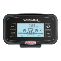
Why does the sprayed surface displayed not match actual sprayed surface on my ARAG Control Unit?
- MmaxwellturnerSep 4, 2025
If the sprayed surface displayed on your ARAG Control Unit does not match the actual sprayed surface, check the boom width setting, the setup of the wheel constant, and the connections to the speed sensor.