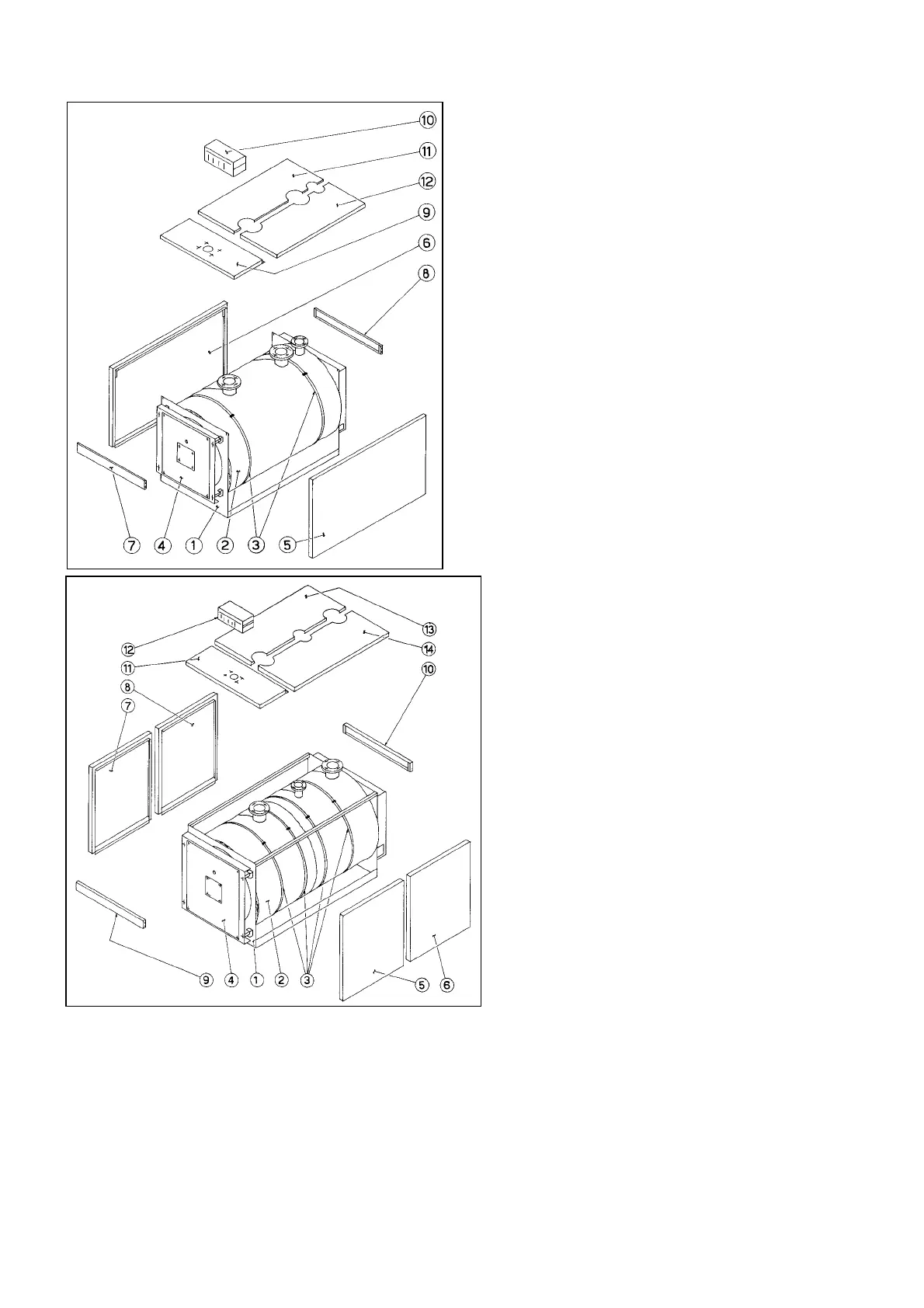
14
PRK 320÷740
− Place the generator Ref.1 in the boiler room and
make all hydraulic and smoke discharge duct
connections.
− Wrap the boiler body with glass fibre insulation
Ref.2, by cutting it near the flow duct and fix it by
means of Ref.3 holding strips. The greater is the
boiler output, the higher is the quantity of the
insulation material.
− The front panel Ref.4 is delivered already fixed to
the door.
− Mount side panels Ref.5 and Ref.6 taking care of
inserting them correctly into Ref.7 and Ref.8, the
front and back duct plates, and the bended part in
the boiler base.
− Insert panels Ref.7 and Ref.8 into Ref.5 and Ref.6
bayonet-joints.
− Insert panels Ref.9 into panels Ref.5 and Ref.6,
toward the boiler front side after having screwed
the switchboard Ref.10 and unrolled cords.
− Insert the half-covers Ref.11 and Ref.12 between
side panels Ref.5 and Ref.6 into side panel Ref.8
and Ref.9.
PRK 830÷3500
− Place the generator Ref.1 in the boiler room
and make all hydraulic and smoke discharge
duct connections.
− Wrap the boiler body with glass fibre insulation
Ref.2, by cutting it near the flow duct and fix it
by means of Ref.3 holding strips. The greater
is the boiler output, the higher is the quantity
of the insulation material.
− The front panel Ref.4 is delivered already fixed
to the door.
− Mount side panels Ref.5, 6 and 8 to the proper
upper cover and boiler base. In boilers with
higher output every side panel consists of 3
panels.
− Insert panels Ref.9 and Ref.10 into side
panels Ref.7 and Ref.5 and Ref.8 and Ref.6
fixing them into their proper bayonet-joints.
− Place the cover Ref.11 by insert it into the side
panels Ref.7 and Ref.5, toward the boiler front
side, after having screwed the switchboard
and unrolled the thermostat cords.
− Place half-covers Ref.13 and 14 among side
panels Ref.5, 6, 7 and 8 by placing them on
the side panel Ref.10 and 11 inward parts.