2
2. TECHNICAL DATA
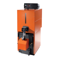
2.1 MAIN SPECIFICATIONS OF MK BOILERS
− Pressurized steel boiler, for heating systems with hot water production up to 95°C.
− Output: from 44 to 269 kW. - Running: light oil-gas.
− Cylindrical furnace, flame inversion, detached from the back duct plate, arc-welded on a copper bar.
− Steel boiler body Fe360 UNI EN 10025/92, completely electro-welded in a CO
2
controlled atmosphere
.
− Steel duct bundle Fe360D UNI EN 10204/2.2, 4 mm thickness.
− Completely adjustable door allowing perfect combustion product tightness.
− Epoxy enamelled boiler jacket, 80 mm thick glass fibre insulation pad to reduce passive heat leakages.
− The switchboard is outside the jacket and is fitted with an operating thermostat, a manual reset safety thermostat, a thermometer, a
minimal temperature thermostat on the circulating pump, an anti-inertia thermostat, a general switch, a circulating pump switch and
burner switch. Rubber sheath with IP 40 minimal protection level.
MK 55 MK 70 MK 80 MK 90 MK 100
kW
kcal/h
44 ÷ 54,7
37.840 ÷ 47.042
50 ÷ 68,4
43.000 ÷ 58.824
62 ÷ 80,1
53.320 ÷ 68.846
75 ÷ 90,3
64.500 ÷ 77.658
90 ÷ 100,1
77.400 ÷ 86.086
kW
kcal/h
48 ÷ 60,2
41.280 ÷ 51.772
54 ÷ 74,7
46.440 ÷ 64.242
67 ÷ 87,4
57.620 ÷ 75.164
80,5 ÷ 98,8
69.230 ÷ 84.968
97 ÷ 109,3
83.420 ÷ 93.998
Combustion chamber volume m³ 0,056 0,056 0,056 0,100 0,100
kW/m³
kcal/h m
3
1.075
924.500
1.334
1.147.179
1.561
1.342.214
988
849.680
1.093
939.980
Exchange surface m² 2,7 2,7 2,7 4,3 4,3
kW/m²
kcal/h m²
20,3
17.423
25,3
21.787
29,7
25.513
21,0
18.060
23,3
20.020
Smoke duct number n° 18 18 18 23 23
Smoke duct diameter Ø est. 1½” 1½” 1½” 1½” 1½”
Boiler weight kg 200 220 220 300 310
Water content l 90 90 90 140 140
Operating pressure bar 5 5 5 5 5
Hydraulic pressure bar 7,5 7,5 7,5 7,5 7,5
Max. operating temperature °C 95 95 95 95 95
Water loss of heat ∆t=15°C mbar
8 10 13 12 14
Combustion chamber pressure mbar 0,12 0,15 0,2 0,24 0,36
Min. efficiency at 100% % 87,5 87,7 87,8 87,9 88
Efficiency at 100% % 90,7 91,5 91,5 91,3 91,5
Min. efficiency at 30% % 85,3 85,5 85,8 85,9 86,1
Efficiency at 30% % 88,5 88,9 89 89,3 90,1
Loss of heat at the chimney with operating burner % 8,2 7,48 7,45 7,61 7,35
Loss of heat at the chimney with burner out % 0,28 0,3 0,26 0,32 0,26
Jacket losses ∆t=50°C %
1,1 1,02 1,05 1,09 1,15
Burner connection (Ø) mm 125 125 125 150 150
Flue connection (Ø) mm 200 200 200 200 200
Min. chimney depression mbar 0,2 0,2 0,2 0,2 0,2
Max. smoke temperature °C 180 185 188 181 185
Smoke temperature in output range °C 141 ÷ 180 148 ÷ 185 151 ÷ 188 146 ÷ 181 155 ÷ 185
CO
2
a gas % 9,8 9,7 10 9,6 9,75
CO a gas ppm 27 24 22 25 19
NOx a gas ppm 43 39 42 45 40
Max. light oil smoke flow rate m³/h 150 180 210 240 270
Max. methane smoke flow rate m³/h 133 159 185 212 239
Light oil burning air volume (practice) m³/h 82 98 114 131 148
Methane burning air volume (practice) m³/h 76 90 105 120 136
Combustion chamber dimension (DiameterXLenght) mm
330 × 650 330 × 650 330 × 650 390 × 830 390 × 830
Thermostat adjustment range °C 55 ÷ 80 55 ÷ 80 55 ÷ 80 55 ÷ 80 55 ÷ 80
Output
Fornace output
Thermal load
Thermal output