6-18
SET-UP AND SAFE OPERATING PROCEDURES
89210000
NOTE
It is recommended to use two Power Cable Assemblies with the N6000 Torch
Complete Package. The cables should be paralleled: connected at the same
points on the Torch Head and the Contactor.
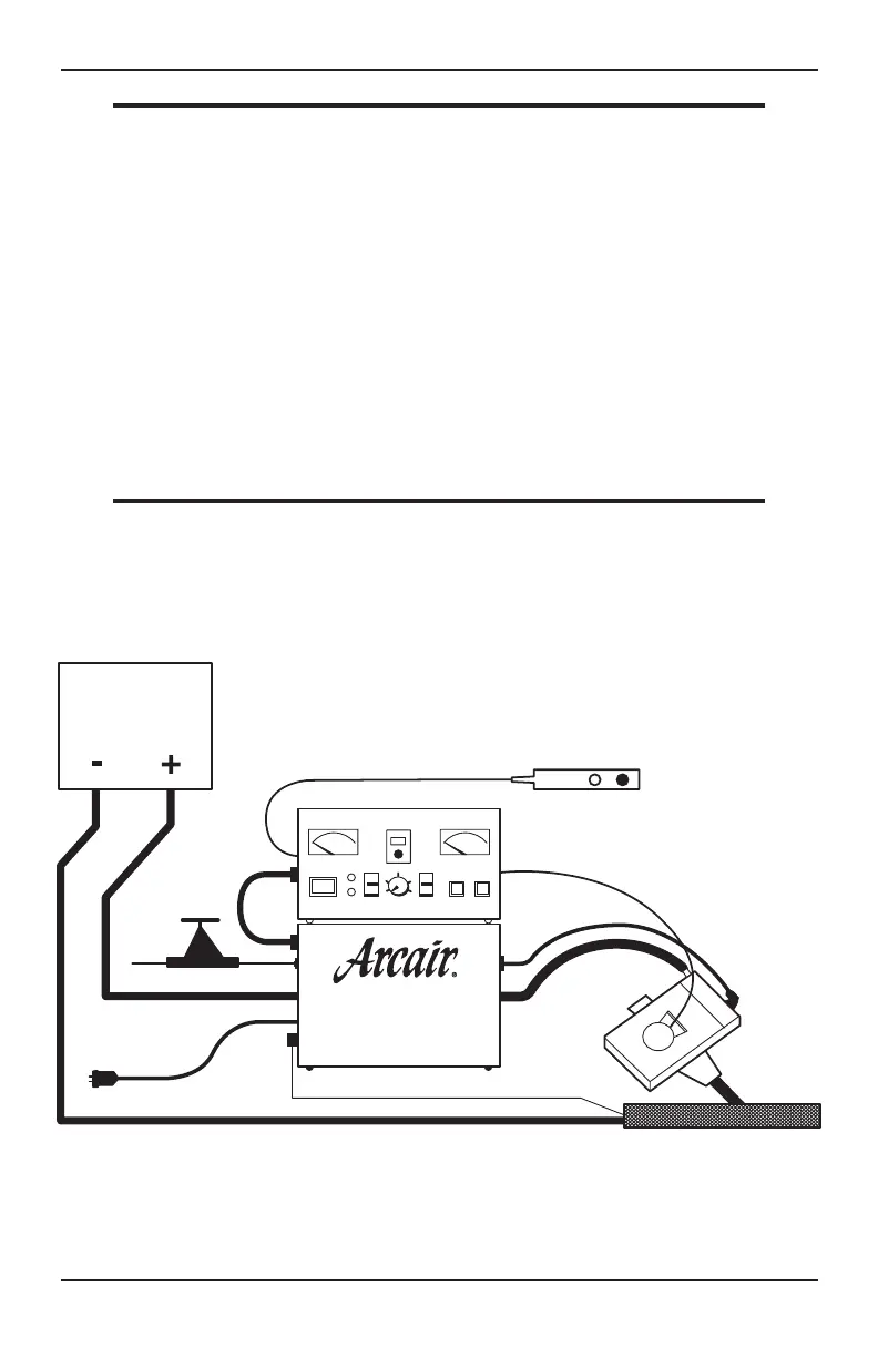
6. Connect the positive (+) cable(s) of the DC power source to the buss-bar terminal on
the back of the Contactor labeled “Power Supply In.”
7. Connect one end of the Air-Hose Assembly to the Torch Head and the other end to “Air
Out” on the Contactor.
8. Connect the Torch motor cable to the receptacle labeled “Head” on the Controller.
9. Connect the negative (-) cable (s) of the DC power source to the workpiece.
10. Connect the signal wire between the ground post of the Contactor and the
workpiece.
NOTICE
Use standard #12 insulated copper wire as your signal wire. It must be long
enough to prevent stress on the Contactor connection.
11. Plug the Carriage System’s grounded power cord into the receptacle labeled “Travel
Carriage Power” on the Controller. Place the Travel Switch on the Controller on
“AUTO.”
CONTROLLER
MOTOR CABLE
REMOTE PENDANT
AIR HOSE
DC POWER
CABLE
TORCH HEAD
WORK PIECE
SIGNAL WIRE
GROUND CABLE (-)
CONTACTOR
AC INPUT POWER
CABLE (+)
INCOMING
AIR LINE
INTERCONNECT
CABLE
POWER
SUPPLY
FIGURE 5 - INSTALLING THE N6000 SYSTEM (DCRP)
Assembly And Installation