Output driver stage
The output driver stage consists of four
OPA2134
dual channel Op-Amps
(IC400-
IC403) each output for instance Front left
channel takes one channel of the op-amp.
The front left and front right channels are
driven down into the Pre-amp board via Pins
1 and 2 of connector Con400 and is fed into
the input switches of the Pre-amp boards
multiplex on Pin 9 from this point the signal is
dealt with as a normal signal input into the
Pre-amp.
Please note: the left and right signals are
seen on the L937 pre-amp card circuit
diagrams as module left and module right.
The Remaining channels are rail clamped to
remove any over-voltage spikes from the rails
and to prevent damage to ancillary equipment
using diode packages
D400 – D405
.
Each output has a mute relay that when
engaged shunts the output to ground at
power up and power down preventing any
spurious D.C levels from leaving the card.
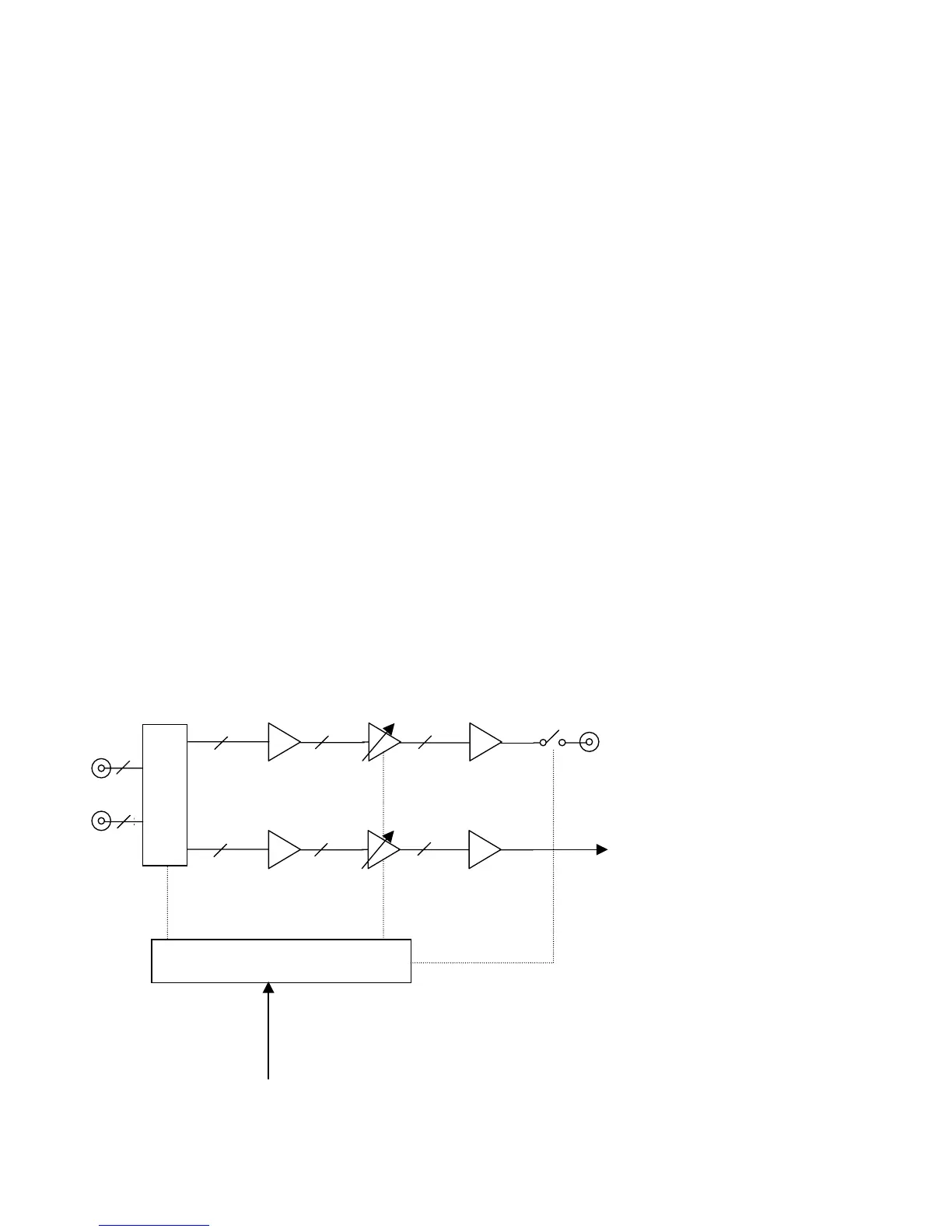
Simplified Block Diagram
Input Mux
Multi-channel inputs
Centre, Sub, Surround
L+R, Back L+R out
8
8
Volume
Front Left and Right
to host.
2
2
Mute
2
Buffer
Buffer
6
6
6
Buffer
Buffer
Volume
Micro controlle
From Host micro controller