0725-736
0725-737
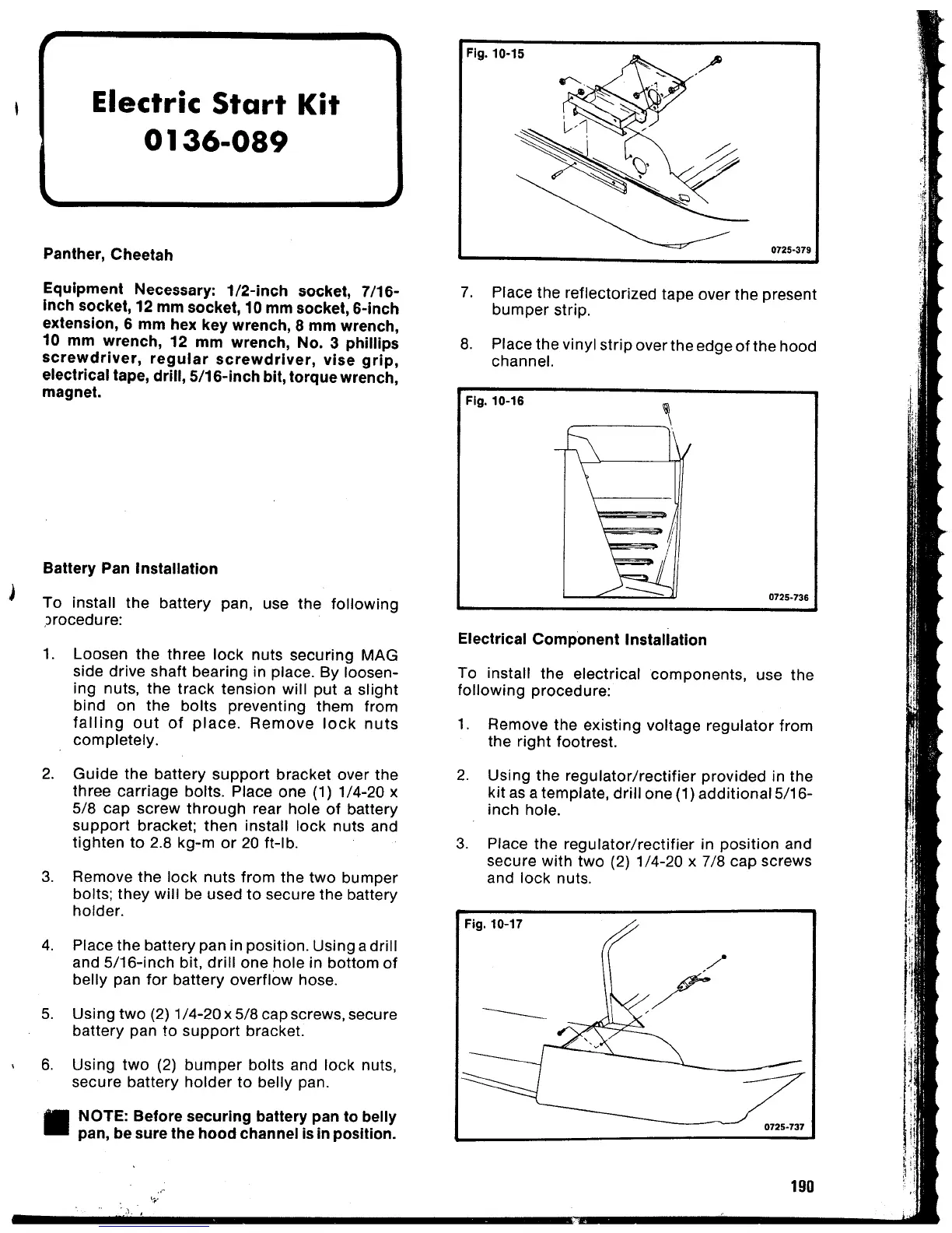
Fig. 10-17
Fig. 10·16
8. Place the vinyl strip overthe edge
of
the hood
channel.
7. Place the reflectorized tape over the present
bumper
strip.
0725-379
Fig. 10·15
190
Electrical
Component
Installation
To install the electrical
components,
use the
following
procedure:
2. Using the
regulator/rectifier
provided in the
kit
as a template,
drill
one (1) additional 5/16-
inch hole.
1. Remove the existing voltage
regulator
from
the right footrest.
3. Place the
regulator/rectifier
in position and
secure
with
two (2) 1/4-20 x 7/8 cap screws
and lock nuts.
Electric
Start
Kit
0136-089
',\.
Panther, Cheetah
Equipment Necessary:
1/2-inch
socket, 7/16-
Inch socket, 12 mm socket, 10 mm socket, 6-lnch
extension, 6 mm hex key wrench, 8 mm wrench,
10 mm wrench, 12 mm wrench,
No.3
phillips
screwdriver,
regular
screwdriver,
vise
grip,
electrical tape, drill,
5/16-lnch
bit,
torque
wrench,
magnet.
II
NOTE: Before securing battery pan to belly
pan, be sure the
hood
channel is In position.
Battery Pan Installation
J
To install the battery pan,
use the
following
orocedure:
1.
Loosen the three lock nuts securing MAG
side drive shaft bearing in place. By loosen-
ing nuts, the track tension will put a slight
bind on the bolts preventing them from
falling
out
of
place.
Remove
lock
nuts
completely.
2.
Guide
the battery
support
bracket over the
three carriage bolts. Place one (1) 1/4-20 x
5/8 cap screw
through
rear hole of battery
support
bracket; then install lock nuts and
tighten
to 2.8 kg-m or 20 It-lb.
3.
Remove the lock nuts from the
two
bumper
bolts; they will be used to secure the battery
holder.
4. Place the battery pan in position. Using a drill
and
5/16-inch
bit,
drill
one hole in bottom of
belly pan
for
battery overflow hose.
5. Using
two
(2) 1/4-20x 5/8 cap screws, secure
battery pan to
support
bracket.
6.
Using
two
(2)
bumper
bolts and lock nuts,
secure battery
holder
to belly pan.