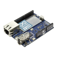
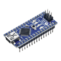
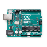
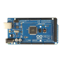
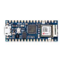
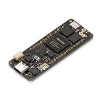
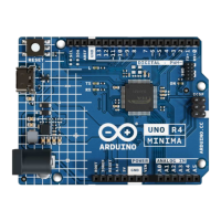
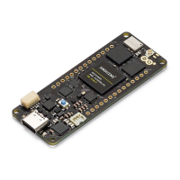
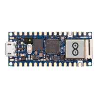
Mechanical Information
14 Pinout
14.1 Three-Pins Header - J1
Pin Function Type Description
1 OFF Digital 3V3 Enable Pin (U6)
2 GND Power Ground
3 VRTC Reset Real Time Clock Battery
14.2 Analog
Pin Function Type Description
1 NC NC Not Connected
2 IOREF IOREF Reference for digital logic V - connected to 3.3V
3 Reset Reset Reset
4 +3V3 Power +3V3 Power Rail
5 +5V Power +5V Power Rail
6 GND Power Ground
7 GND Power Ground
8 VIN Power Voltage Input
9 A0 Analog Analog input 0 /GPIO
10 A1 Analog Analog input 1 /GPIO
11 A2 Analog Analog input 2 /GPIO
12 A3 Analog Analog input 3 /GPIO
13 A4 Analog Analog input 4 /GPIO
14 A5 Analog Analog input 5 /GPIO
15 A6 Analog Analog input 6 /GPIO
16 A7 Analog Analog input 7 /GPIO
17 A8 Analog Analog input 8 /GPIO
18 A9 Analog Analog input 9 /GPIO
19 A10 Analog Analog input 10 /GPIO
20 A11 Analog Analog input 11 /GPIO
21 DAC0 Analog Digital to Analog Converter 0
22 DAC1 Analog Digital to Analog Converter 1
23 CANRX Digital CAN Bus Receive
24 CANTX Digital CAN Bus Transfer
 Loading...
