Rather then requiring a physical press of the reset button before an upload, the Arduino Mega2560 is
designed in a way that allows it to be reset by software running on a connected computer. One of the
hardware flow control lines (DTR) of the ATmega8U2 is connected to the reset line of the ATmega2560 via a
100 nanofarad capacitor. When this line is asserted (taken low), the reset line drops long enough to reset the
chip. The Arduino software uses this capability to allow you to upload code by simply pressing the upload
button in the Arduino environment. This means that the bootloader can have a shorter timeout, as the
lowering of DTR can be well-coordinated with the start of the upload.
This setup has other implications. When the Mega2560 is connected to either a computer running Mac OS X
or Linux, it resets each time a connection is made to it from software (via USB). For the following half-second
or so, the bootloader is running on the Mega2560. While it is programmed to ignore malformed data (i.e.
anything besides an upload of new code), it will intercept the first few bytes of data sent to the board after a
connection is opened. If a sketch running on the board receives one-time configuration or other data when it
first starts, make sure that the software with which it communicates waits a second after opening the
connection and before sending this data.
The Mega contains a trace that can be cut to disable the auto-reset. The pads on either side of the trace can
be soldered together to re-enable it. It's labeled "RESET-EN". You may also be able to disable the auto-reset
by connecting a 110 ohm resistor from 5V to the reset line; see this forum thread for details.
The Arduino Mega has a resettable polyfuse that protects your computer's USB ports from shorts and
overcurrent. Although most computers provide their own internal protection, the fuse provides an extra layer
of protection. If more than 500 mA is applied to the USB port, the fuse will automatically break the connection
until the short or overload is removed.
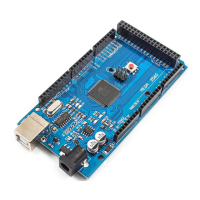
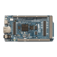
The maximum length and width of the Mega PCB are 4 and 2.1 inches respectively, with the USB connector
and power jack extending beyond the former dimension. Three screw holes allow the board to be attached to
a surface or case. Note that the distance between digital pins 7 and 8 is 160 mil (0.16"), not an even multiple
of the 100 mil spacing of the other pins.
The Mega is designed to be compatible with most shields designed for the Diecimila or Duemilanove. Digital
pins 0 to 13 (and the adjacent AREF and GND pins), analog inputs 0 to 5, the power header, and ICSP
header are all in equivalent locations. Further the main UART (serial port) is located on the same pins (0 and
1), as are external interrupts 0 and 1 (pins 2 and 3 respectively). SPI is available through the ICSP header on
both the Mega and Duemilanove / Diecimila. Please note that I
2
C is not located on the same pins on the
Mega (20 and 21) as the Duemilanove / Diecimila (analog inputs 4 and 5).
 Loading...