Ref. Description Ref. Description
Ref. Description Ref. Description
SJ1 Open solder bridge (VUSB) SJ4 Closed solder bridge (+3V3)
TP Test points xx Lorem Ipsum
3.2 Processor
The Main Processor is a Cortex M0+ running at up to 48MHz. Most of its pins are connected to the external
headers, however some are reserved for internal communication with the wireless module and the on-board
internal I
2
C peripherals (IMU and Crypto).
NOTE: As opposed to other Arduino Nano boards, pins A4 and A5 have an internal pull up and default to be used
as an I
2
C Bus so usage as analog inputs is not recommended.
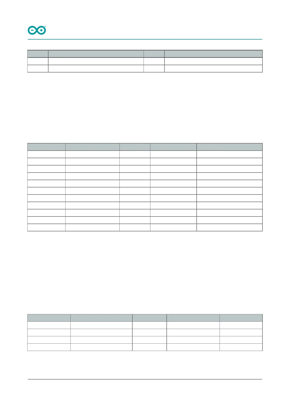
Communication with NINA W102 happens through a serial port and a SPI bus through the following pins.
SAMD21 Pin SAMD21 Acronym NINA Pin NINA Acronym Description
13 PA08 19 RESET_N Reset
39 PA27 27 GPIO0 Attention Request
41 PA28 7 GPIO33 Acknowledge
23 PA14 28 GPIO5 SPI CS
21 GPIO19 UART RTS
24 PA15 29 GPIO18 SPI CLK
20 GPIO22 UART CTS
22 PA13 1 GPIO21 SPI MISO
21 PA12 36 GPIO12 SPI MOSI
31 PA22 23 GPIO3 Processor TX Nina RX
32 PA23 22 GPIO1 Processor RX Nina TX
3.3 WiFi/BT Communication Module
Nina W102 is based on ESP32 and is delivered with a pre-certified software stack from Arduino. Source code for the
firmware is available [9].
NOTE: Reprogramming the wireless module’s firmware with a custom one will invalidate compliance with radio
standards as certified by Arduino, hence this is not recommended unless the application is used in private
laboratories far from other electronic equipment and people. Usage of custom firmware on radio modules is the
sole responsibility of the user.
Some of the module’s pins are connected to the external headers and can be directly driven by ESP32 provided
SAMD21’s corresponding pins are aptly tri-stated. Below is a list of such signals:
SAMD21 Pin SAMD21 Acronym NINA Pin NINA Acronym Description
48 PB03 8 GPIO21 A7
14 PA09 5 GPIO32 A6
8 PB09 31 GPIO14 A5/SCL
7 PB08 35 GPIO13 A4/SDA
 Loading...