12 GHA l Switchgear extension and replacement of a panel
3 Extension of an existing double busbar switchgear system
Treat all new contact surfaces in accordance with the Assembly Instruc-6.
tions. Treat the new busbar clamping contacts for both busbar systems in
accordance with the Assembly Instructions and insert them into the new
panel (busbar tubes) to be lined up (Fig. 5, item 1). Position panel on the
base frame in accordance with the space assignment plan.
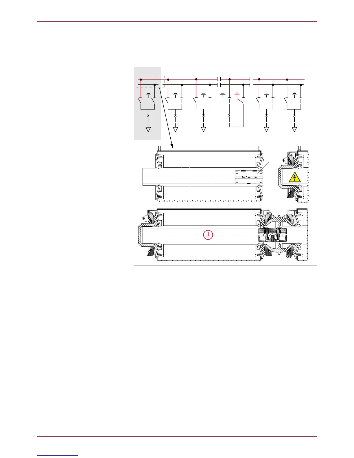
BB2 (top)
BB1 (rear)
Fig. 5
New panel lined-up on the left-hand end
– busbar 1 (rear) completely connected and ready to operate (protective cover on
busbar end not shown)
– busbar 2 (top) not yet connected
1 Busbar clamping contacts
Align new panel and screw-fasten it to the adjacent panel and the base 7.
frame (see Assembly Instructions).
Mount busbar connection for busbar 1 completely with clamping contacts 8.
(see Assembly Instructions) (Fig. 5).
If applicable, mount further panels in accordance with items 6 - 7. Mount 9.
both busbar systems BB1 and BB2 completely on the new panels (see
Assembly Instructions).
BB1
BB2
 Loading...