23
4 Replacement of a panel within a switchgear system
GHA l Switchgear extension and replacement of a panel
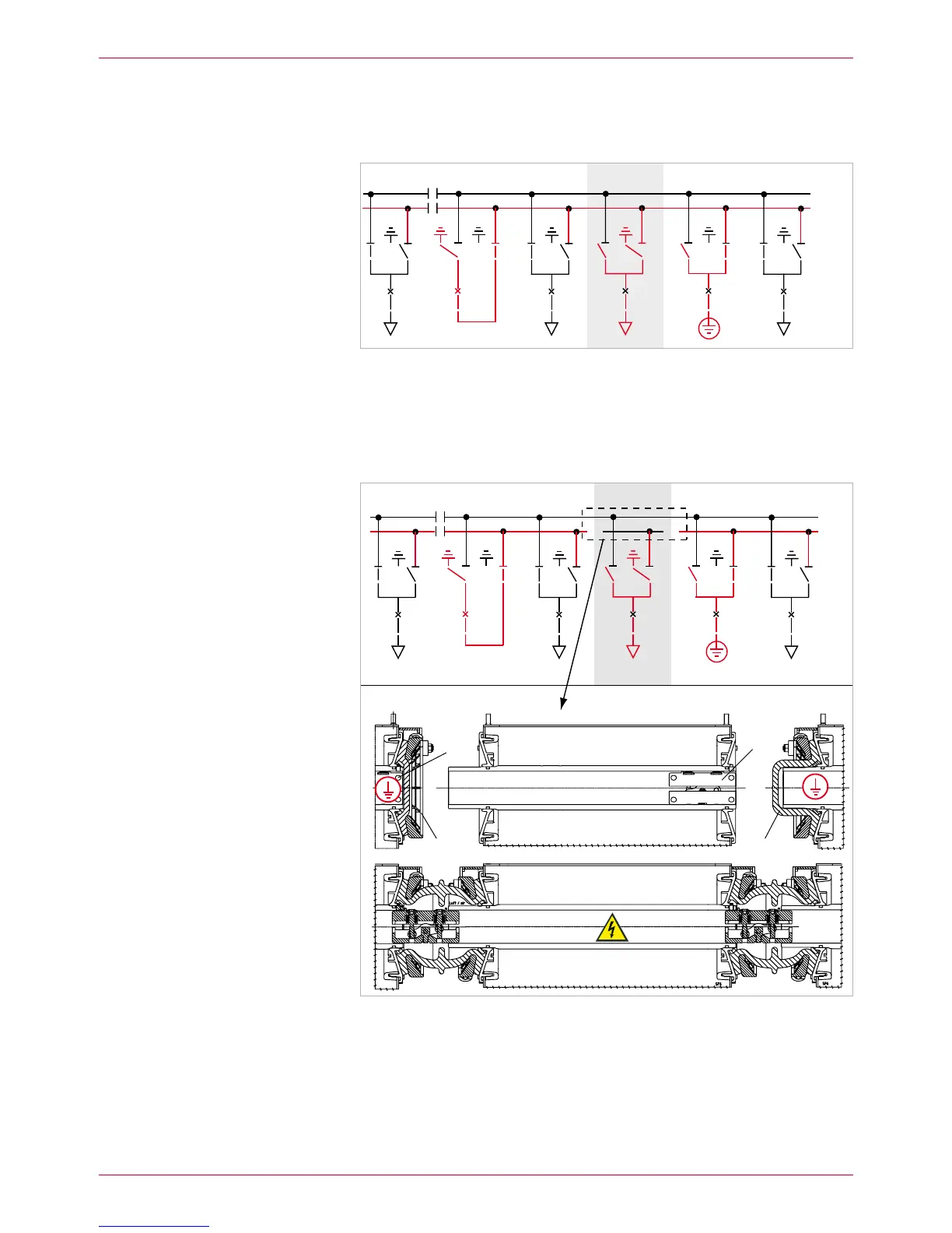
4. Earth busbar 2 on both sides of the panel concerned (7). To this effect,
earth busbar 2 additionally via the outgoing feeder of panel 8 (see Operat-
ing Instructions) (Fig. 15).
Attach a clear identification to busbars 1 and 2 of the adjacent panels.
Fig. 15
Busbar 2 with additional earthing device in panel 8
In the faulty panel, disconnect the busbar links of the busbar concerned 5.
(shown: BB2) on both sides (3 x left-hand and 3 x right-hand, Fig. 16).
Push clamping contacts into the busbar tubes of the appropriate left-hand
panel.
BB2 (top)
BB1 (rear)
Fig. 16
Panel 7: Busbar 2 has been disconnected.
The busbars of the adjacent panels were closed by means of surge-proof end caps.
Busbar 1 in operation, busbar 2 still earthed, but ready to operate.
surge-proof end caps1
busbar clamping contacts2
Removing the faulty panel
BB1
BB2
BB1
BB2
 Loading...