Remove silicone sleeves of the busbar connections.6.
Clean and grease the open busbar bushings on the adjacent panels and 7.
close them using surge-proof end caps (Fig. 16, item 1).
Left-hand adjacent panel: narrow end caps
Right-hand adjacent panel: high end caps
Thus, both sections of busbar 2 are ready to operate.
Reroute all outgoing feeder panels to 8. BB2.
Warning!
Risk of injury in case of operating errors!
For safety reasons, all persons must be located in front of the
switchgear during switching operations!
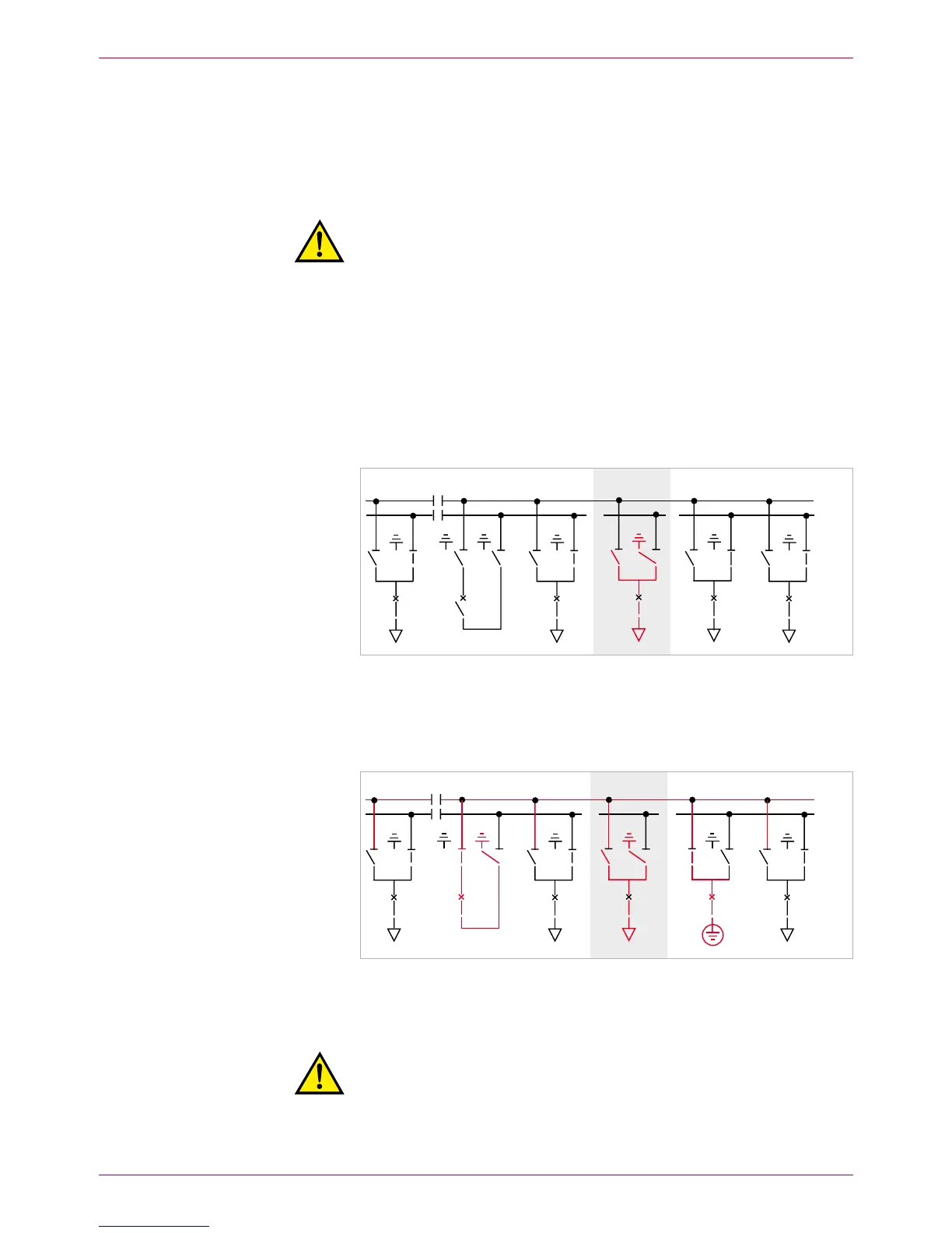
Cancel both – BB2 earthings.
Switch bus coupler ON. –
Switch disconnectors in the incoming feeder panels to – BB2.
Switch disconnectors in outgoing feeder panels - except those of the –
faulty panel 7 – to BB2 (Fig. 17).
In the outgoing feeder panels, open the disconnectors for BB1. –
In the incoming feeder panels, open the disconnectors for BB1. –
Switch off the bus coupler. –
Fig. 17
Both sections of busbar 2 are in operation
Earth 9. BB1 on both sides of the panel concerned (shown in Fig. 18: busbar
earthing through bus coupler and via outgoing feeder of panel 8, see also
Operating Manual, Chapter 6.7).
Fig. 18
Busbar 1 earthed via bus coupler (5).
Mount additional earthing device to busbar 1 (panel 8).
All other panels switched to busbar 2.
Warning!
Risk of injuries. The upper busbar (BB2) is in operation and the rear
busbar (BB1) is now earthed. Comply precisely with all safety provi-
sions. Check busbar identification.
BB1
BB2
BB1
BB2
 Loading...