25
4 Replacement of a panel within a switchgear system
GHA l Switchgear extension and replacement of a panel
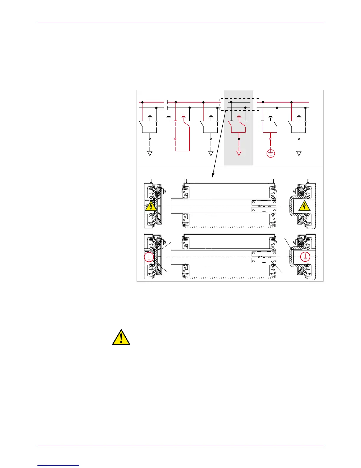
Release the busbar connections (10. BB1, rear busbar) in the faulty panel. Slip
the clamping contacts into the busbar tubes of the left-hand panel (Fig.
19, item 2) and remove the silicone sleeves.
Clean and grease the open busbar bushings on the adjacent panels and
close them using surge-proof end caps (Fig. 19, item 1).
Left-hand adjacent panel: flat end caps
Right-hand adjacent panel: high end caps
Thus, both sections of busbar 1 are ready to operate (Fig. 19).
BB2 (top)
BB1 (rear)
Fig. 19
BB1 divided into two sections, each of which is closed with surge-proof terminations
and operative again (BB1 sections still earthed)
Surge-proof end caps1
Busbar clamping contacts2
Recommission 11. BB1:
Warning!
Risk of injury in case of operating errors.
For safety reasons, all persons must be located in front of the
switchgear during switching operations!
Cancel both – BB1 earthings.
Switch bus coupler ON. –
Switch disconnectors in the incoming feeder panels to – BB1.
Both sections of busbars 1 and 2 are in operation. The faulty panel 7 was dis-
connected from both busbar systems (Fig. 20).
BB1
BB2
 Loading...