26 GHA l Switchgear extension and replacement of a panel
4 Replacement of a panel within a switchgear system
BB2 (top)
BB1 (rear)
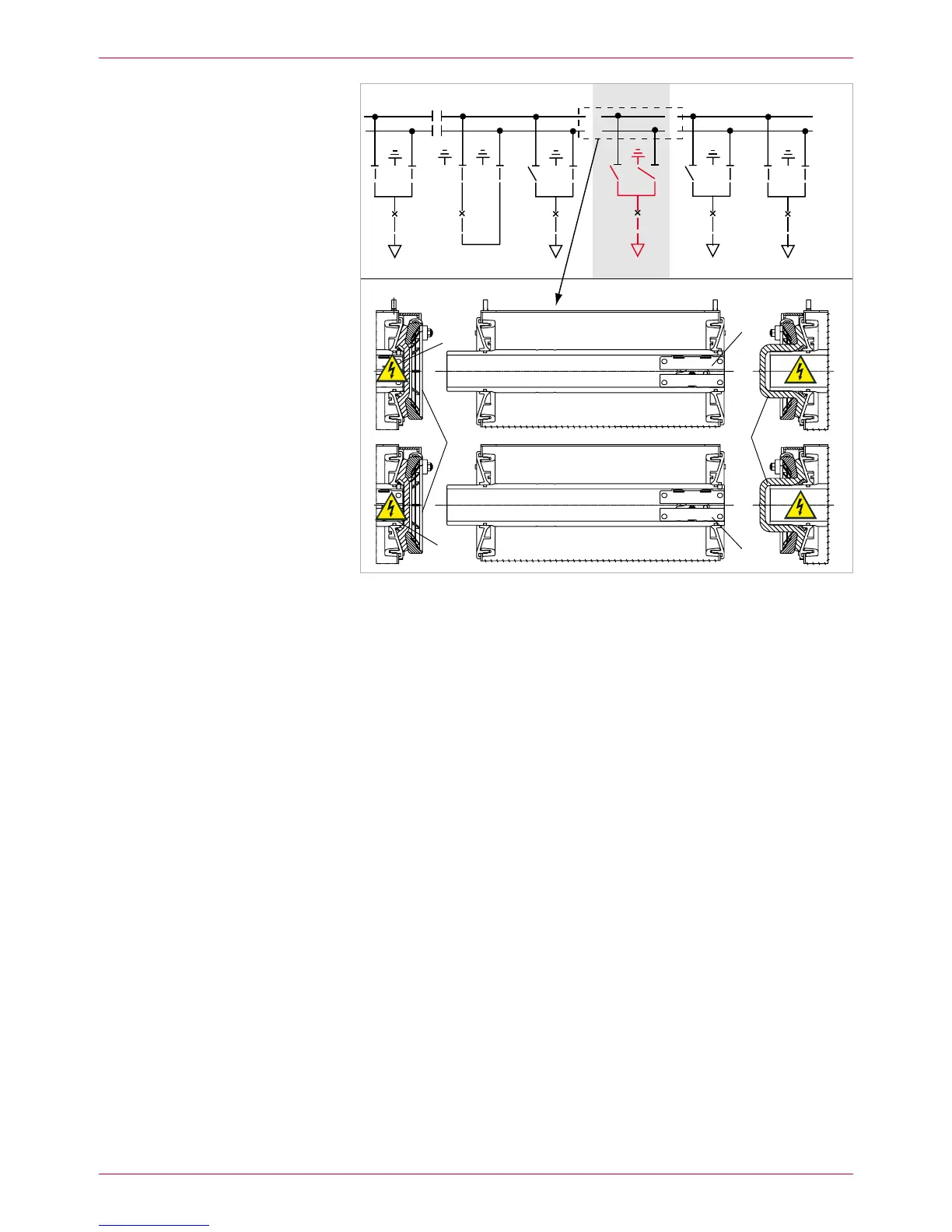
Fig. 20
Panel 7: Both busbars are disconnected. The busbars of the adjacent panels were
closed by means of surge-proof end caps. Busbar 1 in operation, busbar 2 in operation.
Surge-proof end caps1
Busbar clamping contacts2
Disconnect all the other panel connections:12.
panel screw fastenings to adjacent panels / base frame –
earth conductor –
The left-hand and right-hand switchgear sections must be connected
sufficiently to the building earth (see Assembly Instructions, Chapter
4.9).
low-voltage connectors and ring lines –
high-voltage terminals –
Remove panel.13.
14. On the new or repaired panel, treat the busbar contact areas and the
clamping contacts in accordance with the Assembly Instructions. Insert the
clamping contacts into the busbar tubes (Fig. 20, item 2) and reposition
the panel on the base frame.
Insert new panel
BB1
BB2
 Loading...