28 GHA l Switchgear extension and replacement of a panel
4 Replacement of a panel within a switchgear system
Screw-fasten panels to adjacent panels and base frame (see Assembly 15.
Instructions).
Earth 16. BB1 sections.
Warning!
For safety reasons, all persons must be located in front of the
switchgear during switching operations!
Switch all outgoing feeder panels to BB2. After switching, open the disconnec-
tors in the incoming feeder panels for BB1. Switch off the bus coupler.
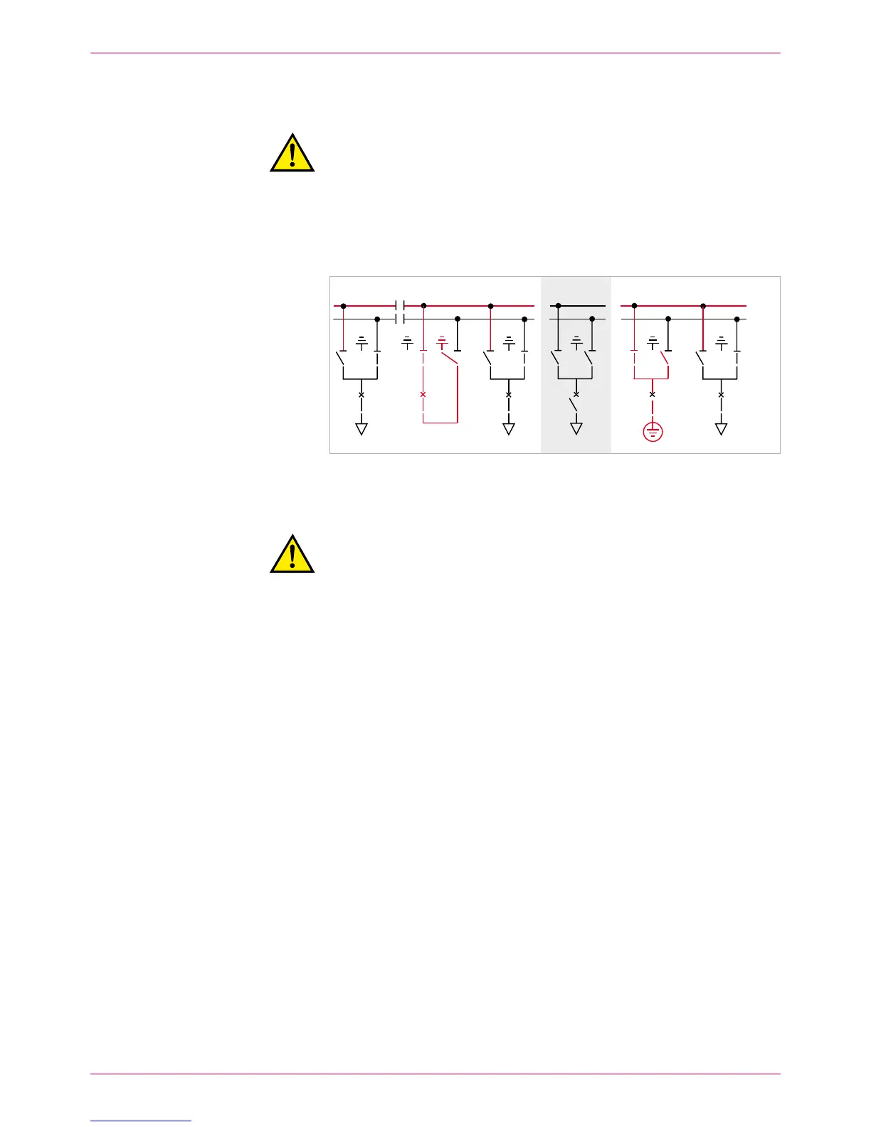
Earth BB1 on both sides of the panel concerned (shown in Fig. 22: busbar
earthing through bus coupler and via outgoing feeder of panel 8, see also Op-
erating Manual, Chapter 6.7).
Fig. 22
Busbar 1: both sections earthed (e.g. left-hand busbar section with bus coupler [5] and
right-hand section with earthing device in panel 8). All the other panels are located on
busbar 2.
Warning!
Risk of injuries. Now, the upper busbar (BB2) is in operation and the
rear busbar (BB1) is earthed. Comply precisely with all safety provi-
sions. Check busbar identification.
On busbar 1 (rear), remove the busbar end caps of the two adjacent pan-17.
els. Clean and grease busbar bushings.
Clean and grease silicone link sleeve, insert it under preload and mount it 18.
on the right-hand side of each panel.
BB1
BB2
 Loading...