32 GHA l Switchgear extension and replacement of a panel
4 Replacement of a panel within a switchgear system
On busbar 2 (top), remove the busbar end caps of the two adjacent pan-23.
els. Clean and grease busbar bushings.
Clean and grease silicone link sleeve, insert it under preload and mount it
on the right-hand side of each panel.
Re-establish all BB2 connections to the adjacent panels (6 x) completely.
Release the silicone sleeves and fasten them to the adjacent panel (see
Assembly Instructions).
All the other assembly steps are to be performed in accordance with the 24.
Assembly Instructions:
final steps –
high-voltage terminals –
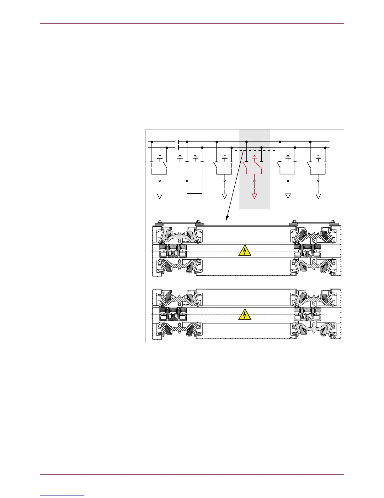
Switch bus coupler ON. Thus, both busbars are operative again (Fig. 26).
BB2 (top)
BB1 (rear)
Fig. 26
Replacement of panel complete. New panel (7) inserted and both busbars with full
continuity and in operation again
BB1
BB2
 Loading...