31
4 Replacement of a panel within a switchgear system
GHA l Switchgear extension and replacement of a panel
Earth 22. BB2 on both sides of the panel concerned (shown in Fig. 25: busbar
earthing through bus coupler and via outgoing feeder of panel 8, see also
Operating Manual, Chapter 6.7).
Warning!
Risk of injuries. Now, the rear busbar (BB1) is in operation and the
upper busbar (BB2) earthed. Comply precisely with all safety provi-
sions. Check busbar identification.
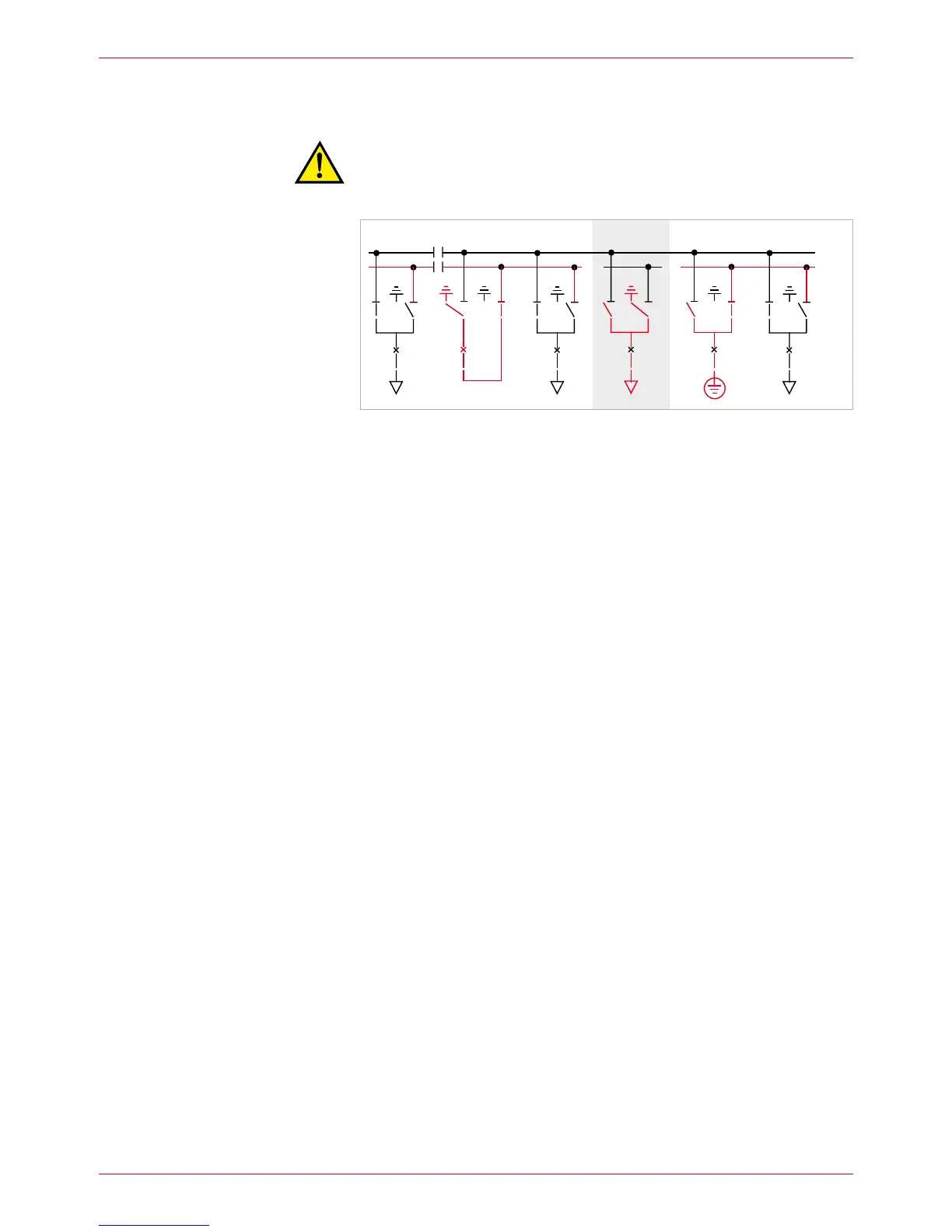
Fig. 25
Busbar 2: both sections earthed (e.g. left-hand busbar section with bus coupler [5] and
right-hand section with earthing device in panel 8). All the other panels are located on
busbar 1.
BB1
BB2
 Loading...