The further steps for assembly are to be performed in accordance with the 20.
Assembly Instructions:
connect the earth bars. –
connect the low-voltage cables (ring lines, external customer cables). –
Commission replacement panel:
comply with Assembly Instructions (Chapter 10). –
check operating functions and interlocks of switching devices. –
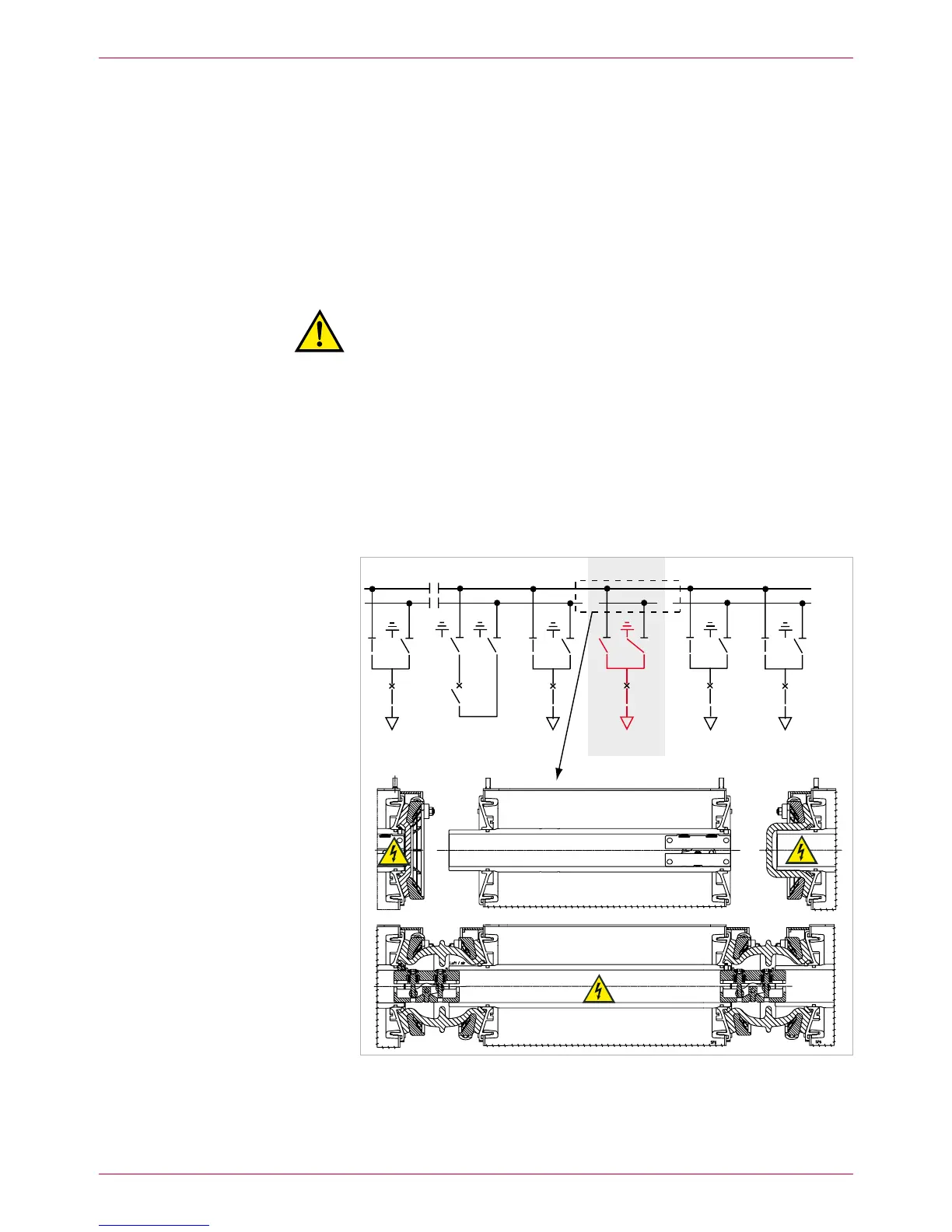
Set replacement panel to „EARTHED“ position (Fig. 24).
Thus, busbar 1 is ready to operate again.
Reroute21. outgoing feeder panels to BB1 (Fig. 24):
Warning!
Risk of injury in case of operating errors.
For safety reasons, all persons must be located in front of the
switchgear during switching operations!
Cancel both – BB1 earthings.
Switch bus coupler ON. –
Switch disconnectors in the incoming feeder panels to – BB1.
Switch disconnectors in the outgoing feeder panels to – BB1
(Fig. 24).
In the outgoing feeder panels, open the disconnectors for BB2. –
In the incoming feeder panels, open the disconnectors for BB2. –
Switch off the bus coupler. –
 Loading...