Pxxxx/EN SS/E11
Safety Section 3/8
3. SYMBOLS AND EXTERNAL LABELS ON THE EQUIPMENT
For safety reasons the following symbols and external labels, which may be used on the
equipment or referred to in the equipment documentation, should be understood before the
equipment is installed or commissioned.
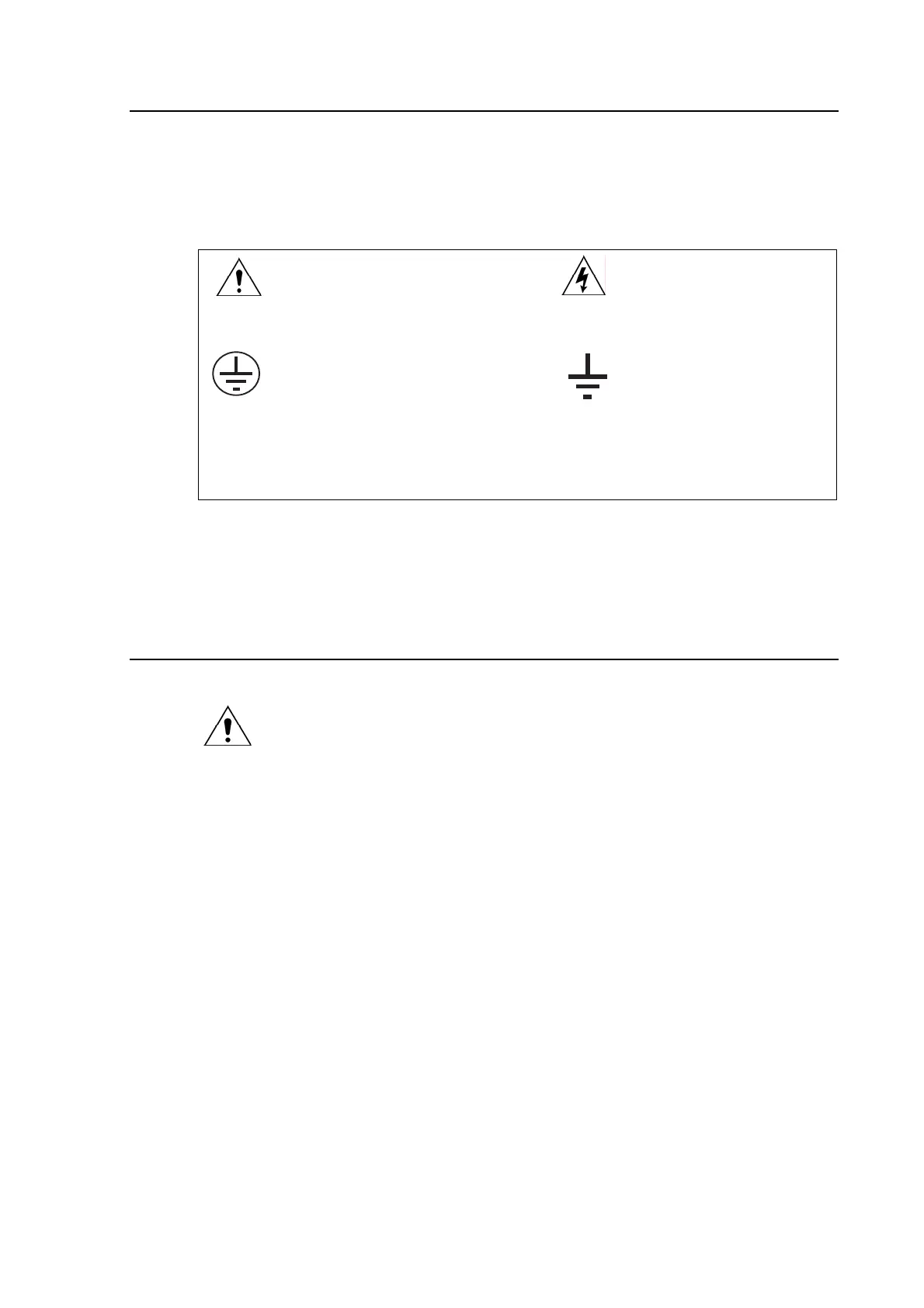
3.1 Symbols
Caution: refer to equipment documentation Caution: risk of electric shock
Protective Conductor (*Earth) terminal. Functional/Protective Conductor Earth
terminal
Note – This symbol may also be used for a Protective Conductor (Earth) terminal if that
terminal is part of a terminal block or sub-assembly e.g. power supply.
*NOTE: THE TERM EARTH USED THROUGHOUT THIS GUIDE IS THE
DIRECT EQUIVALENT OF THE NORTH AMERICAN TERM
GROUND.
3.2 Labels
See Safety Guide (SFTY/4L M/E11) for typical equipment labeling information.
4. INSTALLING, COMMISSIONING AND SERVICING
Equipment connections
Personnel undertaking installation, commissioning or servicing work for this
equipment should be aware of the correct working procedures to ensure safety.
The equipment documentation should be consulted before installing,
commissioning, or servicing the equipment.
Terminals exposed during installation, commissioning and maintenance may
present a hazardous voltage unless the equipment is electrically isolated.
Any disassembly of the equipment may expose parts at hazardous voltage, also
electronic parts may be damaged if suitable electrostatic voltage discharge (ESD)
precautions are not taken.
If there is unlocked access to the rear of the equipment, care should be taken by
all personnel to avoid electric shock or energy hazards.
Voltage and current connections should be made using insulated crimp
terminations to ensure that terminal block insulation requirements are maintained
for safety.
Watchdog (self-monitoring) contacts are provided in numerical relays to indicate
the health of the device. AREVA T&D strongly recommends that these contacts
are hardwired into the substation's automation system, for alarm purposes.
To ensure that wires are correctly terminated the correct crimp terminal and tool
for the wire size should be used.
The equipment must be connected in accordance with the appropriate connection
diagram.
 Loading...


