P92x/EN FT/E11 Technical Guide
User Guide
Page 30/110 MiCOM P921-P922-P923
8. MEASUREMENTS
All measured quantities are displayed in primary values (true RMS values, up to the
10
th
harmonic). They are refreshed once per second.
8.1 Configuration
According to the connection scheme, which is selected, the phase or line voltages will
be measured and then displayed.
8.1.1 "3Vpn" configuration (3VTs "Phase-Neutral")
The 3 phase voltages VA, VB and VC will be measured by the MiCOM relay.
The derived quantities are the symetrical components of the voltage : zero-sequence
voltage (V0), positive and negative sequences voltages (V1 and V2 for MiCOM P922
and P923).
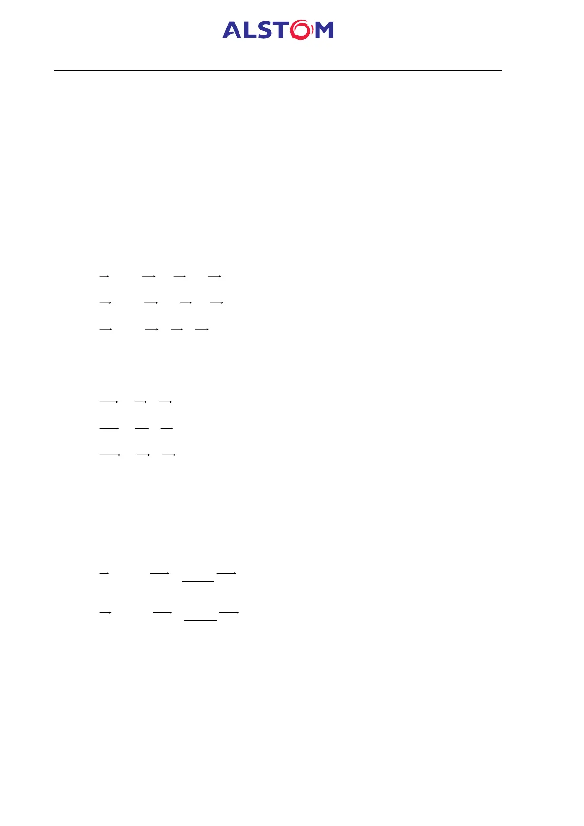
)VC²aVBaVA(3/11V ++= with a = e
j2
p
/3
)VCaVB²aVA(3/12V ++=
)VCVBVA(3/10V ++=
If the protection mode is “Phase-Phase”, the line voltages Vab, Vbc and Vca will be
used in the protection algorithms. These line voltages are derived from the formulas
below :
)VAVB(VAB -=
)VBVC(VBC -=
)VCVA(VCA -=
8.1.2 "3Vpp+Vr" configuration (3 "Phase-Phase" VTs + 1 residual VT)
The 3 line voltages Vab, Vbc, Vca and the residual voltage Vr are then measured by
the MiCOM relay.
The derived quantities are : positive and negative sequences voltages (V1 and V2,
only for MiCOM P922 and P923) :
)VBC
)a21(
)1a(
UAB(3/11V
+
-
+-=
with a = e
j2
p
/3
)VBC
)a21(
)a2(
UAB(3/12V
+
+
+-=
The only protection mode, which is available in this configuration, is the "Phase-
Phase" mode.