Technical Guide P92x/EN CT/E11
Modbus Protocol
MiCOM P921-P922-P923 Page 17/118
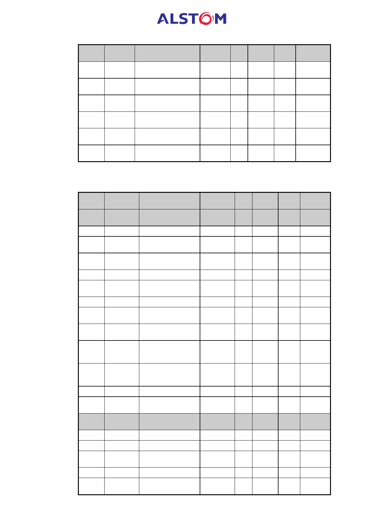
Address Group Description
Settings
range
Step Unit Format
Default
settings
0060 Memorisation of the
latched output relays (1)
F6
0061 Reset of the latched output
relays (1)
F6
0062-
0063
Reserved
0064 df/dt protection
information
F58
0065 Memorization of the df/dt
protection information
F58
0066 to
006F
Reserved
1.7.3 Page 1 : Remote settings
Read and write access
Address Group Description
Settings
range
Step Unit Format
Default
settings
0100 Remote
settings
Address 1 to 255 1 - F1 1
0101 Reserved - - - - -
0102 Password
characters 1 and 2
32 -127 1 - F10 AA
0103 Password
characters 3 and 4
32 -127 1 - F10 AA
0104 Frequency 50-60 10 Hz F1 50
0105 to
108
Reserved
0109 Default display 1-4 1 - F26 1
010A User reference
(characters 1 and 2)
32-127 1 F10 AL
010B User reference
(characters 3 and 4)
32-127 1 F10 ST
010C Fault number to be
displayed (P922 & P923
only)
1-5 1 F31 5
010D Configuration of the
validation edge of the
logic inputs
0F120
010E Reserved
010F Type of input voltage Of
the logic inputs
0-1 1 F50 0
CB
supervision
(P922-P923 ) only
0110 CB operation number 1 F1
0111 CB operating time 1 1/100 sec F1
0112 to
117
Reserved
0118 CB closing time 1 1/100 sec F1
0119 to
011E
Reserved