P92x/EN CT/E11 Technical Guide
Modbus Protocol
Page 42/118 MiCOM P921-P922-P923
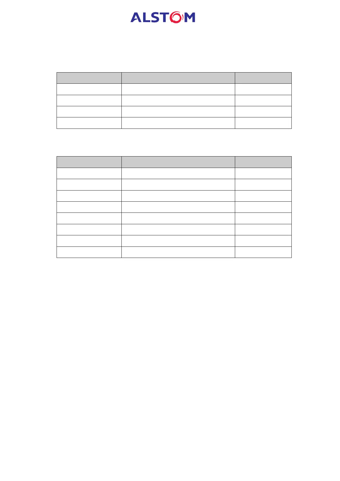
1.7.19 Page 41h: selection of Frequency Disturbance Record and channel (MiCOM P923
only).
Read access only
Address Contents Format
4100h Average Va Vb Vc F71
4101h Measured period F71
4102h Logic inputs/outputs F71
4103h Sample period F71
1.7.20 Pages 42h to 49h : Datas of Frequency Disturbance Record (MiCOM P923 only).
Read access only
Address Contents Format
4200 to 42FAh 250 frequency disturbance data words F72
4300 to 43FAh 250 frequency disturbance data words F72
4400 to 44FAh 250 frequency disturbance data words F72
4500 to 45FAh 250 frequency disturbance data words F72
4600 to 46FAh 250 frequency disturbance data words F72
4700 to 47FAh 250 frequency disturbance data words F72
4800 to 48FAh 250 frequency disturbance data words F72
4900 to 49FAh 250 frequency disturbance data words F72
N.B. : - The disturbance data pages contain values of one channel
from one given disturbance record.
- significance of the value according to the type of channel :
V
A, VB, VC = 16 bits values
Period = time between 2 samples in ms
Logical channel =
bit 0 = RL1 ( Trip Relay )
bit 1 = RL2
bit 2 = RL3
bit 3 = RL4
bit 4 = watchdog
bit 5 = RL5
bit 6 = RL6
bit 7 = RL7
bit 8 = RL8
bit 9 = reserved
bit 10 = logic input 1
bit 11 = logic input 2
bit 12 = logic input 3
bit 13 = logic input 4
bit 14 = logic input 5
bit 15 = Validity of the frequency measurement