P92x/EN GS/E11 Technical Guide
Getting Started
Page 14/18 MiCOM P921-P922-P923
aB
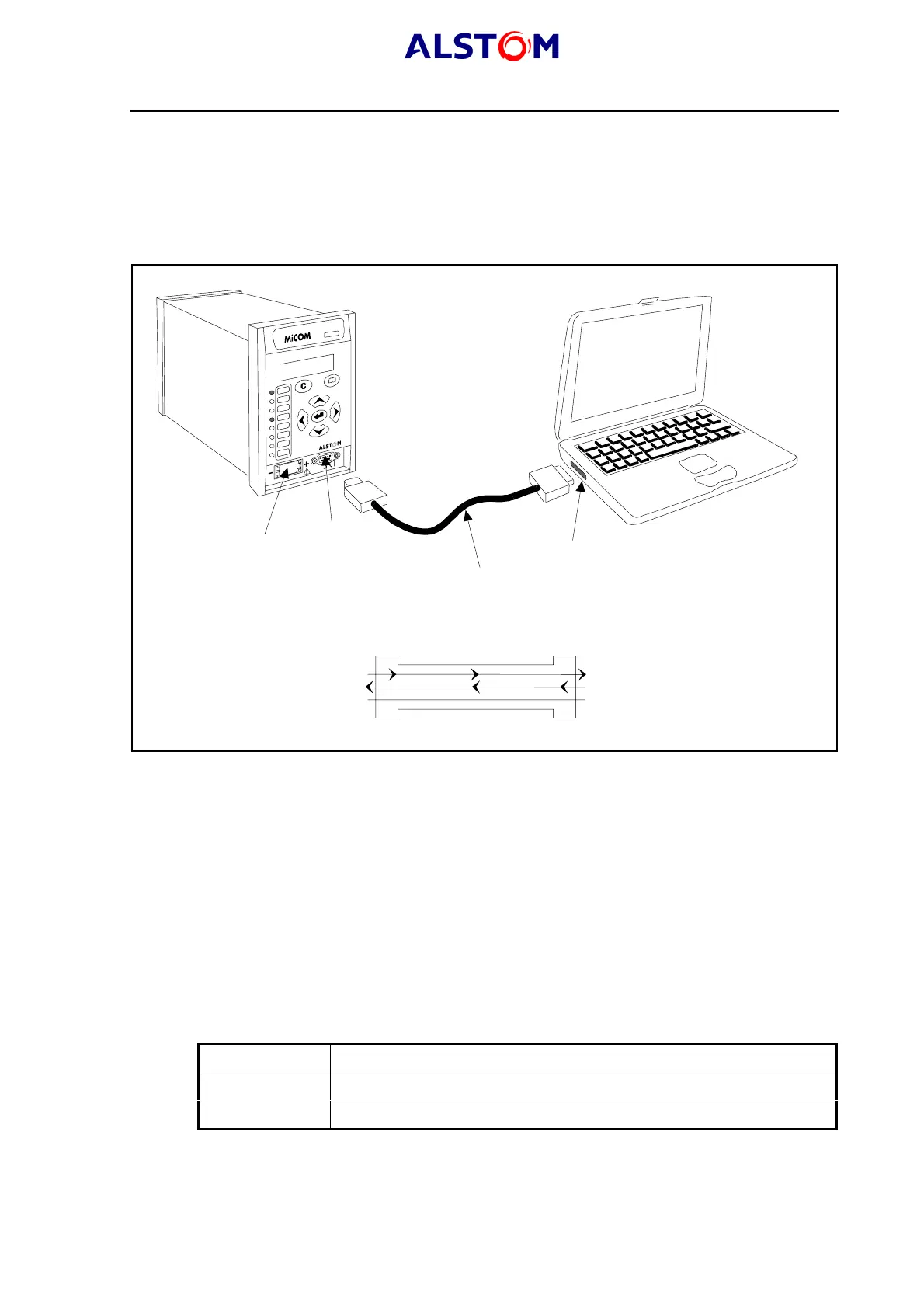
13. PC CONNECTION – LOCAL COMMUNICATIONS
The MiCOM S1 access software is used to set the relay locally from a laptop.
13.1 Configuration of the connection
The configuration is shown below :
MiCOM P921 relay
Laptop
Serial communication port (COM1 or COM2)
Serial data connector (up to 15 m)
Battery
9 pin front port
P0394ENa
Serial data connector
DCE
Pin 2 Tx
Pin 3 Rx
Pin 5 0V
DTE
Pin 2 Rx
Pin 3 Tx
Pin 5 0V
P0387ENa
FIGURE 4 : PC CONNECTION SHOWN ASSUMING 9 WAY SERIAL PORT
The front communication port is provided by a 9-pin female D-type connector located
under the bottom hinged cover. It provides RS232 serial data communication
(asynchronous RS232 connection according the IEC870 requirements) and is
intended for use with a PC locally to the relay (up to 15m distance) as shown in
Figure 4 : this is for one to one connection and this is not suitable for permanent
connection.
13.2 Configuration of the relay and of the laptop
Having made the physical connection from the relay to the PC, the PC’s
communication settings must be configured to match those of the relay. The relay’s
communication settings for the front port are fixed as shown in the table below:
Protocol ModBus
Baud rate 19,200 bits/s
Message format 11 bit - 1 start bit, 8 data bits, 1 parity bit (even parity), 1 stop bit
The address of the relay must be set in the "COMMUNICATIONS" menu.