P92x/EN CM/E11 Techncal Guide
Commissioning Guide
Page 20/28 MiCOM P921-P922-P923
abcd
5.4 "Under/overfrequency" function tests
5.4.1 Wiring diagram
Refer to the diagram used for the "Phase over/undervoltage protection” function tests.
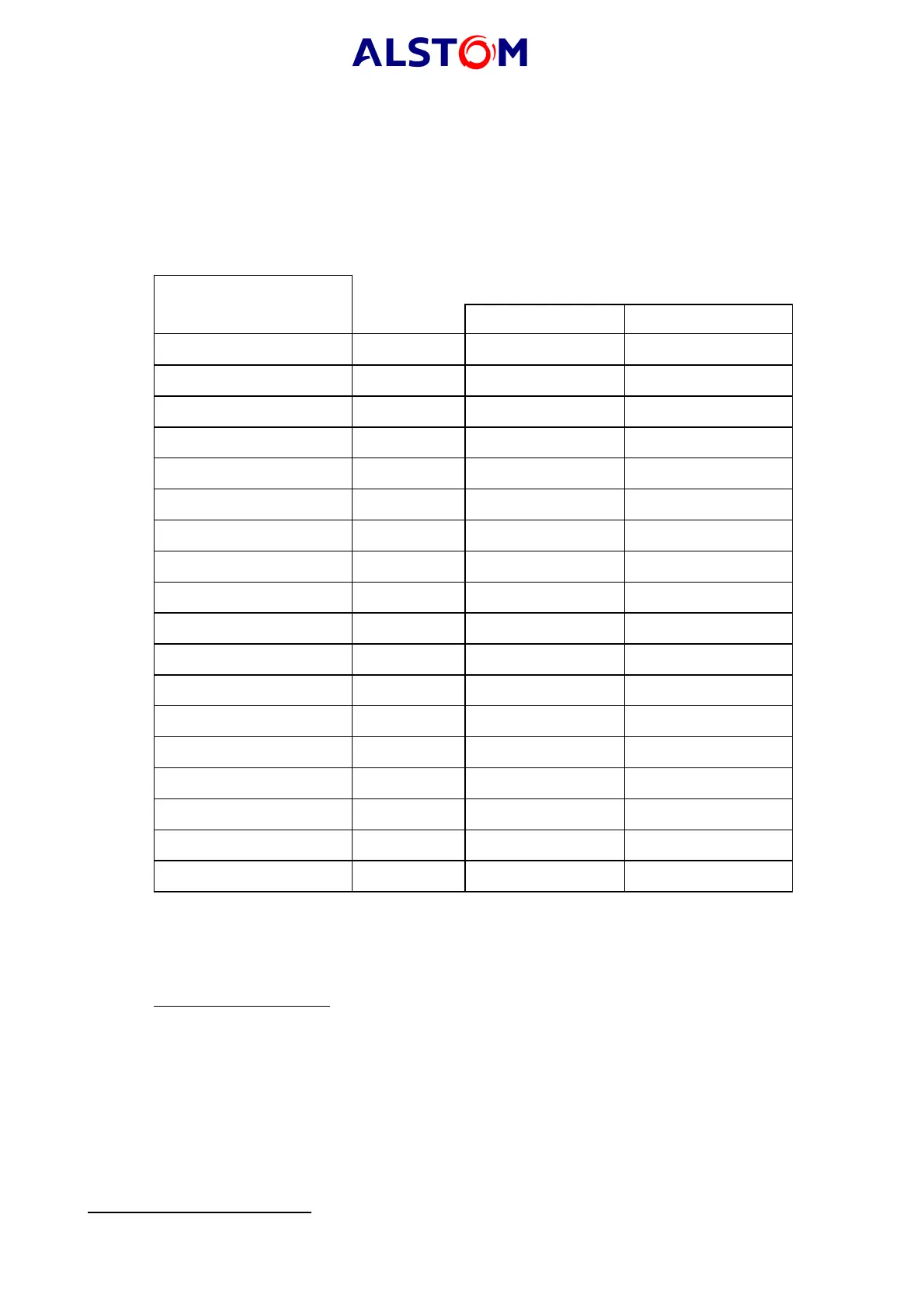
5.4.2 MiCOM P922-P923 relay parameters
Only configure the frequency for one of the six stages available.
Settings
[81] FREQUENCY
Default values
Group 1 Group 2
1
st
stage activated No
No / 81< / 81>
*
No / 81< / 81> *
1
st
frequency stage 50 Hz Hz Hz
1
st
stage time delay 0.04s Secs Secs
2
nd
stage activated No No / 81< / 81> * No / 81< / 81> *
2
nd
frequency stage 50 Hz Hz Hz
2
nd
stage time delay 0.04s Secs Secs
3
rd
stage activated No No / 81< / 81> * No / 81< / 81> *
3
rd
frequency stage 50 Hz Hz Hz
3
rd
stage time delay 0.04s Secs Secs
4
th
stage activated No No / 81< / 81> * No / 81< / 81> *
4
th
frequency stage 50 Hz Hz Hz
4
th
stage time delay 0.04s Secs Secs
5
th
stage activated No No / 81< / 81> * No / 81< / 81> *
5
th
frequency stage 50 Hz Hz Hz
5
th
stage time delay 0.04s Secs Secs
6
th
stage activated No No / 81< / 81> * No / 81< / 81> *
6
th
frequency stage 50 Hz Hz Hz
6
th
stage time delay 0.04s Secs Secs
5.4.3 Test example: stage (f1>) or (f1<)
First program the 1
st
frequency stage at (81>) (overfrequency), then configure it at
(81<) (underfrequency). Then measure the values given below.
Values to be measured:
1. stage (f1>) or (f1<)
2. time delay (tf1>) or (tf1<)
*
Delete as appropriate