Technical Guide P92x/EN CO/E11
Connection Diagrams
MiCOM P921-P922-P923 Page 3/10
aB
1. ANALOGUE INPUTS
The MiCOM P921-P922 and P923 relays have 4 voltage inputs : one voltage input
for the residual voltage and 3 phase voltage inputs.
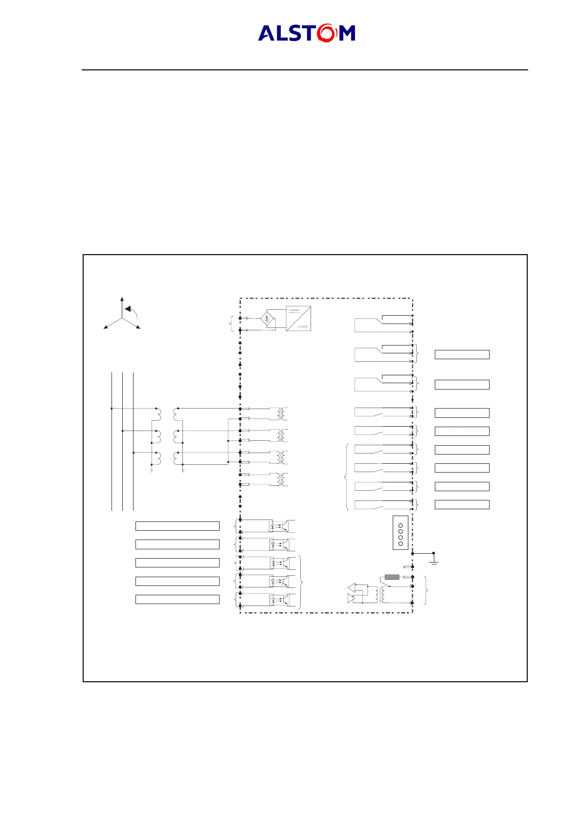
1.1 VT inputs
The following figures present different configurations of VTs.
1.1.1 3VTs (phase-neutral) configuration
Select the « 3V
PN
» configuration in the « CONFIGURATION » menu and in the
« GENERAL » sub-menu.
The 3 phase voltages VA, VB, VC are then measured by the MiCOM relay.
33
34
+
-
Notes :
(1) Additional hardware for MiCOM P922 and P923 relay
(2) Additional hardware for MiCOM P922 and P923 relay
Scheme representing MiCOM relay off
41
42
43
44
45
46
49
50
22
24
26
28
19
17
21
23
27
25
WD
37
35
36
RL1
6
4
2
RL2
12
10
8
29
31
32
-
30
+
_
C
B
A
Phase rotation
Programmable inputs :
See note 1
P0389ENa
Power supply
Watchdog
Output contacts programmable
RL3
16
14
RL4
20
18
RL5
3
1
RL6
7
5
RL7
9
11
RL8
13
15
4 programmable LEDs
See note 2
Earth
connection
Communication port RS485
3VTs CONFIGURATION (Phase-Neutral)
LEDs
(* System end resistance.
For last relay, connect 30 and 32 together).
*
RL2
RL1
EL1
EL2
EL3
EL4
EL5
RL3
RL4
RL5
RL6
RL7
RL8
MiCOM P92
*
+
_
+
_
+
_
+
_
+
_
FIGURE 1 : 3VTs CONNECTION